How to Use b-l475: Examples, Pinouts, and Specs
Introduction
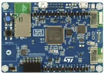
The B-L475 is a development board built around the STM32L475 microcontroller, which is part of the STM32L4 series. This microcontroller is designed for ultra-low-power applications, making the B-L475 an excellent choice for IoT (Internet of Things) projects. The board integrates various connectivity options, including Wi-Fi and Bluetooth, and features a range of onboard sensors, such as temperature, humidity, and motion sensors. These features make it ideal for prototyping smart devices, environmental monitoring systems, and wearable technology.
Explore Projects Built with b-l475


Explore Projects Built with b-l475
Common Applications and Use Cases
- IoT device prototyping
- Environmental monitoring systems
- Smart home automation
- Wearable technology
- Industrial sensor networks
- Low-power data logging systems
Technical Specifications
Key Technical Details
- Microcontroller: STM32L475VG (ARM Cortex-M4, 80 MHz, with FPU)
- Flash Memory: 1 MB
- RAM: 128 KB
- Connectivity:
- Wi-Fi (ISM43362-M3G-L44 module)
- Bluetooth Low Energy (BLE)
- USB OTG
- Sensors:
- Temperature and humidity sensor (HTS221)
- Magnetometer and accelerometer (LSM6DSL)
- Pressure sensor (LPS22HB)
- Time-of-flight ranging sensor (VL53L0X)
- Power Supply: 5V via USB or external power source
- Operating Voltage: 3.3V
- Expansion: Arduino Uno V3-compatible headers, STMod+ connector
- Debugging: Integrated ST-LINK/V2-1 debugger/programmer
Pin Configuration and Descriptions
The B-L475 board features multiple pin headers for connectivity and expansion. Below is the pinout for the Arduino Uno V3-compatible headers:
| Pin | Name | Description |
|---|---|---|
| D0 | RX | UART Receive (connected to STM32L475 UART) |
| D1 | TX | UART Transmit (connected to STM32L475 UART) |
| D2-D13 | Digital I/O | General-purpose digital input/output pins |
| A0-A5 | Analog Inputs | Analog input pins (connected to STM32L475 ADC channels) |
| 3.3V | 3.3V Output | 3.3V power output (regulated from USB or external power source) |
| 5V | 5V Output | 5V power output (directly from USB or external power source) |
| GND | Ground | Ground connection |
| VIN | Input Voltage | External power input (7-12V recommended) |
The STMod+ connector provides additional connectivity for external modules, such as displays or communication peripherals.
Usage Instructions
How to Use the B-L475 in a Circuit
Powering the Board:
- Connect the board to a computer or USB power adapter using a micro-USB cable.
- Alternatively, supply power through the VIN pin (7-12V recommended).
Programming the Board:
- Install STM32CubeIDE or another compatible IDE.
- Connect the board to your computer via USB. The integrated ST-LINK/V2-1 debugger will be detected.
- Write your code in the IDE and upload it to the board.
Using Onboard Sensors:
- The onboard sensors are connected to the STM32L475 via I2C or SPI. Use the STM32 HAL (Hardware Abstraction Layer) or LL (Low Layer) libraries to interface with them.
- For example, the HTS221 temperature and humidity sensor can be accessed via I2C at address
0x5F.
Expanding Functionality:
- Use the Arduino Uno V3-compatible headers to connect external shields or modules.
- The STMod+ connector can be used for additional peripherals, such as displays or communication modules.
Important Considerations and Best Practices
- Power Supply: Ensure the board is powered within the recommended voltage range to avoid damage.
- Debugging: Use the integrated ST-LINK/V2-1 debugger for programming and debugging. Ensure the correct drivers are installed on your computer.
- Sensor Calibration: Some onboard sensors may require calibration for accurate readings. Refer to the sensor datasheets for details.
- Low-Power Mode: To maximize battery life in IoT applications, utilize the STM32L475's low-power modes.
Example Code for Arduino IDE
The B-L475 can be programmed using the Arduino IDE with the STM32 core installed. Below is an example of reading data from the onboard HTS221 temperature and humidity sensor:
#include <Wire.h>

// HTS221 I2C address
#define HTS221_ADDR 0x5F

// HTS221 register addresses
#define WHO_AM_I 0x0F
#define TEMP_OUT_L 0x2A
#define TEMP_OUT_H 0x2B

void setup() {
  Wire.begin(); // Initialize I2C communication
  Serial.begin(9600); // Start serial communication

  // Check if HTS221 is connected
  Wire.beginTransmission(HTS221_ADDR);
  Wire.write(WHO_AM_I);
  Wire.endTransmission();
  Wire.requestFrom(HTS221_ADDR, 1);
  if (Wire.available()) {
    byte id = Wire.read();
    if (id == 0xBC) { // Expected ID for HTS221
      Serial.println("HTS221 detected!");
    } else {
      Serial.println("HTS221 not detected!");
    }
  }
}

void loop() {
  // Read temperature data
  Wire.beginTransmission(HTS221_ADDR);
  Wire.write(TEMP_OUT_L);
  Wire.endTransmission();
  Wire.requestFrom(HTS221_ADDR, 2);

  if (Wire.available() == 2) {
    int16_t temp = Wire.read() | (Wire.read() << 8);
    float temperature = temp / 256.0; // Convert to Celsius
    Serial.print("Temperature: ");
    Serial.print(temperature);
    Serial.println(" °C");
  }

  delay(1000); // Wait 1 second before next reading
}
Troubleshooting and FAQs
Common Issues and Solutions
Board Not Detected by Computer:
- Ensure the USB cable is functional and supports data transfer.
- Verify that the ST-LINK/V2-1 drivers are installed on your computer.
Unable to Program the Board:
- Check that the board is in programming mode. Press the reset button if necessary.
- Ensure the correct board and port are selected in your IDE.
Incorrect Sensor Readings:
- Verify the sensor connections and I2C/SPI addresses.
- Calibrate the sensors if required, following the datasheets.
Power Issues:
- Ensure the board is powered within the recommended voltage range.
- Check for loose connections or insufficient power supply.
FAQs
Can I use the B-L475 with Arduino shields? Yes, the board features Arduino Uno V3-compatible headers for easy integration with shields.
Does the board support battery power? Yes, you can power the board using an external battery connected to the VIN pin.
What IDEs are compatible with the B-L475? The board is compatible with STM32CubeIDE, Keil, IAR, and the Arduino IDE (with the STM32 core installed).
How do I enable low-power modes? Use the STM32 HAL or LL libraries to configure the microcontroller's low-power features. Refer to the STM32L4 reference manual for details.