
How to Use F4V3S Plus: Examples, Pinouts, and Specs
 Design with F4V3S Plus in Cirkit Designer
Introduction
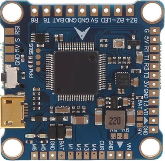
The F4V3S Plus, manufactured by Sudemota, is a high-performance flight controller designed specifically for multirotors and drones. It features advanced stabilization algorithms, seamless integration with multiple sensors, and support for a wide range of communication protocols. This makes it an excellent choice for both hobbyists and professionals seeking precise control and reliable performance in aerial applications.
Explore Projects Built with F4V3S Plus
 Open Project in Cirkit Designer
 Open Project in Cirkit Designer
 Open Project in Cirkit Designer
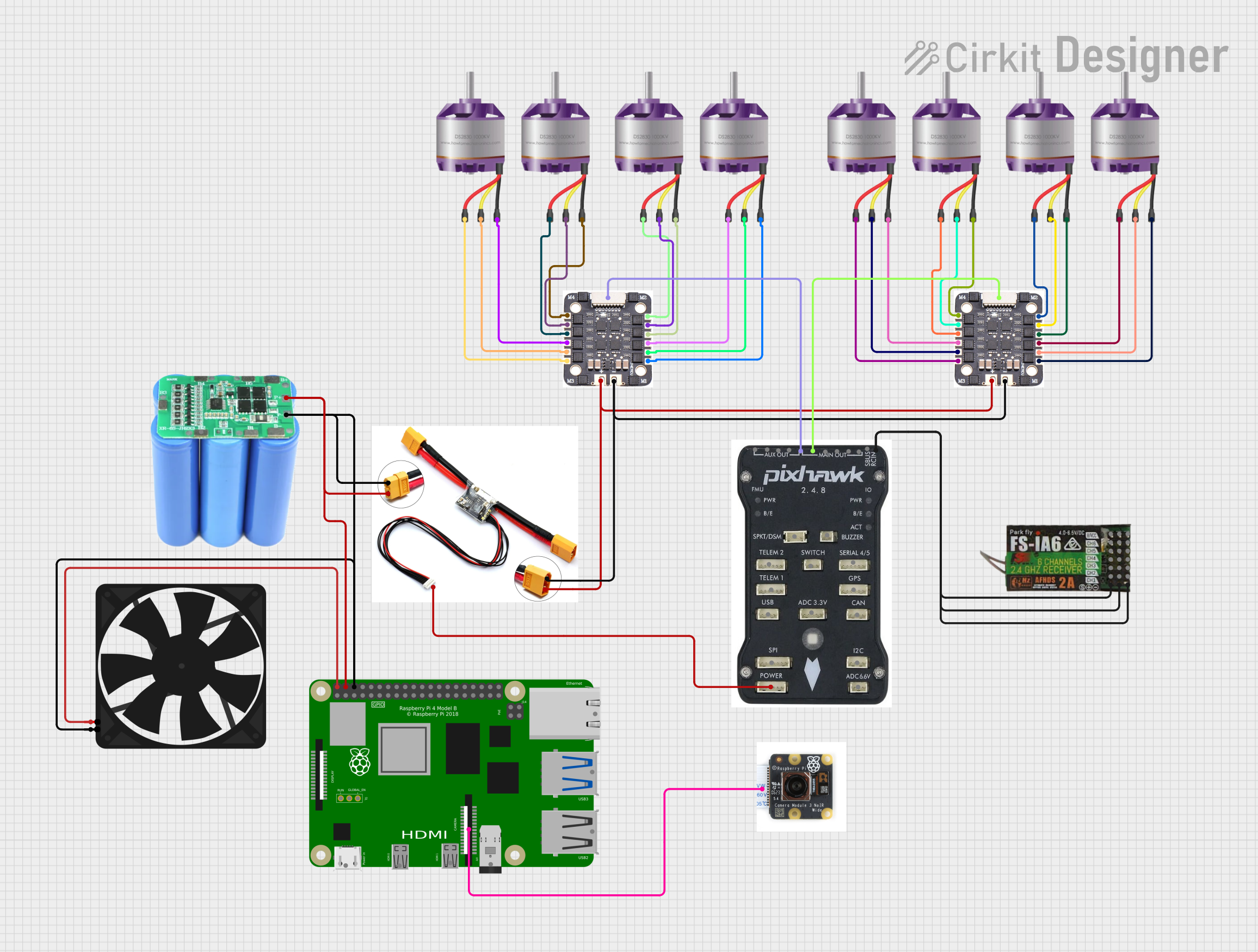 Open Project in Cirkit Designer
Explore Projects Built with F4V3S Plus
Open Project in Cirkit DesignerOpen Project in Cirkit DesignerOpen Project in Cirkit DesignerOpen Project in Cirkit DesignerCommon Applications and Use Cases
- Multirotor drones (quadcopters, hexacopters, octocopters)
- Autonomous aerial vehicles (AAVs)
- FPV (First-Person View) racing drones
- Aerial photography and videography platforms
- Research and development in UAV (Unmanned Aerial Vehicle) systems
- Educational projects in robotics and aerodynamics
Technical Specifications
The F4V3S Plus is packed with features to ensure optimal performance and compatibility with a variety of drone setups.
Key Technical Details
| Parameter | Specification |
|---|---|
| Processor | STM32F405RGT6 (32-bit ARM Cortex-M4) |
| IMU (Inertial Measurement Unit) | MPU6000 (6-axis gyro and accelerometer) |
| Input Voltage Range | 5V - 16.8V (2S to 4S LiPo batteries) |
| Communication Protocols | UART, I2C, SPI, SBUS, DSMX, CRSF |
| PWM Outputs | 8 channels |
| Flash Memory | 16MB onboard |
| USB Interface | Micro-USB |
| Dimensions | 36mm x 36mm |
| Mounting Hole Spacing | 30.5mm x 30.5mm (M3 screws) |
| Weight | 7 grams |
Pin Configuration and Descriptions
The F4V3S Plus features a well-labeled pinout for easy integration into drone systems.
Main Pinout Table
| Pin Name | Description |
|---|---|
| GND | Ground connection |
| 5V | 5V power output for peripherals |
| VBAT | Battery voltage input (2S-4S LiPo) |
| M1 - M8 | Motor outputs (PWM signals) |
| UART1 RX | UART1 receive pin for telemetry or peripherals |
| UART1 TX | UART1 transmit pin for telemetry or peripherals |
| UART2 RX | UART2 receive pin for external devices |
| UART2 TX | UART2 transmit pin for external devices |
| I2C SDA | I2C data line for external sensors |
| I2C SCL | I2C clock line for external sensors |
| SBUS | Serial input for SBUS receivers |
| DSMX | Serial input for DSMX receivers |
| CRSF | Input for Crossfire receivers |
| BOOT | Bootloader mode selection |
Usage Instructions
The F4V3S Plus is designed for ease of use, but proper setup is essential for optimal performance. Follow these steps to integrate the flight controller into your drone system.
Step 1: Wiring and Connections
- Power Supply: Connect the VBAT pin to the positive terminal of your LiPo battery (2S-4S). Ensure the GND pin is connected to the battery's ground.
- Motors: Connect your ESC (Electronic Speed Controller) signal wires to the M1-M8 pins, depending on the number of motors in your drone.
- Receiver: Connect your receiver to the appropriate input pin (e.g., SBUS, DSMX, or CRSF).
- Peripherals: Attach additional sensors or devices (e.g., GPS, barometer) to the I2C or UART pins as required.
Step 2: Firmware Installation
- Download the latest firmware for the F4V3S Plus from the Sudemota website.
- Connect the flight controller to your computer via the Micro-USB port.
- Use a compatible configuration tool (e.g., Betaflight Configurator) to flash the firmware onto the flight controller.
Step 3: Configuration
- Open the configuration tool and connect to the flight controller.
- Calibrate the accelerometer and set up the desired flight modes.
- Configure the motor outputs and receiver settings.
- Test all connections and ensure proper functionality before flight.
Step 4: Arduino Integration (Optional)
The F4V3S Plus can be interfaced with an Arduino UNO for custom applications, such as additional sensor processing or telemetry.
Example Code for UART Communication
#include <SoftwareSerial.h>

// Define RX and TX pins for UART communication
SoftwareSerial mySerial(10, 11); // RX = pin 10, TX = pin 11

void setup() {
  // Initialize serial communication
  Serial.begin(9600); // Monitor communication
  mySerial.begin(115200); // Communication with F4V3S Plus

  Serial.println("Starting communication with F4V3S Plus...");
}

void loop() {
  // Send a test message to the flight controller
  mySerial.println("Hello, F4V3S Plus!");

  // Check for incoming data from the flight controller
  if (mySerial.available()) {
    String data = mySerial.readString();
    Serial.println("Received from F4V3S Plus: " + data);
  }

  delay(1000); // Wait 1 second before sending the next message
}
Best Practices
- Always use a high-quality LiPo battery to ensure stable power delivery.
- Secure all connections to prevent disconnections during flight.
- Perform a pre-flight check to verify all systems are functioning correctly.
- Update the firmware regularly to benefit from the latest features and bug fixes.
Troubleshooting and FAQs
Common Issues and Solutions
Flight Controller Not Powering On
- Ensure the VBAT and GND connections are secure.
- Verify the battery voltage is within the supported range (5V-16.8V).
Motors Not Spinning
- Check the motor connections to the M1-M8 pins.
- Verify the ESCs are properly calibrated and powered.
No Communication with Configuration Tool
- Confirm the Micro-USB cable is functional and supports data transfer.
- Ensure the correct COM port is selected in the configuration tool.
Unstable Flight
- Recalibrate the accelerometer and check the PID (Proportional-Integral-Derivative) settings.
- Inspect the drone for mechanical issues, such as loose propellers or frame damage.
FAQs
Q: Can the F4V3S Plus support GPS modules?
A: Yes, the flight controller supports GPS modules via the UART or I2C interface.
Q: What is the maximum number of motors supported?
A: The F4V3S Plus supports up to 8 motors, making it suitable for octocopters.
Q: Is the F4V3S Plus compatible with Betaflight?
A: Yes, the flight controller is fully compatible with Betaflight and other popular configuration tools.
Q: How do I enter bootloader mode?
A: Hold the BOOT pin to ground while powering on the flight controller to enter bootloader mode.
By following this documentation, users can effectively integrate and operate the F4V3S Plus flight controller in their drone systems.