Cirkit Designer
Your all-in-one circuit design IDE
Home /
Component Documentation
How to Use ESP32_Relay_X4_V1.1: Examples, Pinouts, and Specs
Introduction
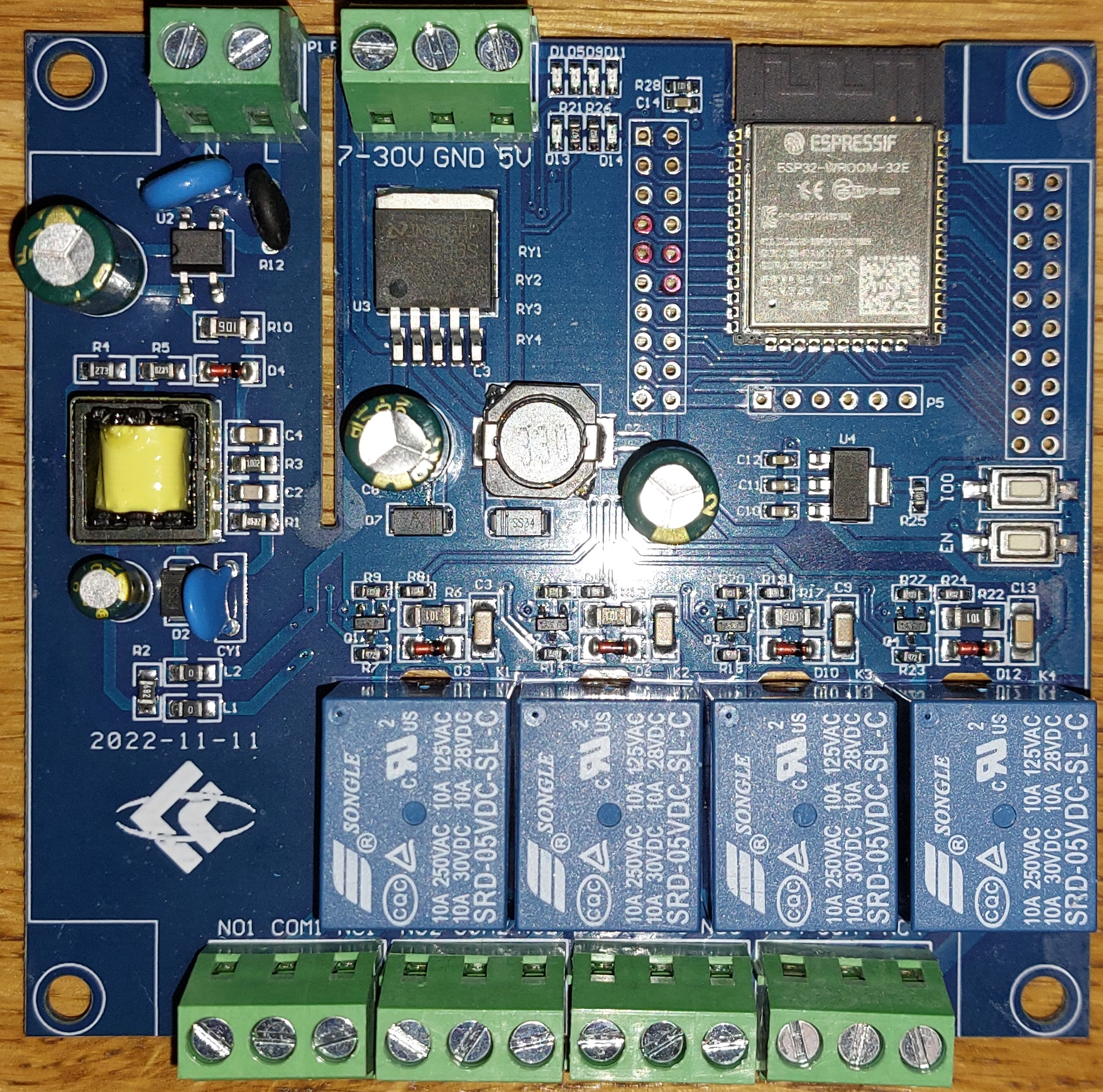
The ESP32_Relay_X4_V1.1 is a versatile module manufactured by LC that integrates an ESP32 microcontroller with four relays. This combination allows for wireless control of multiple high-power devices via Wi-Fi or Bluetooth. The module is ideal for home automation, industrial control, and IoT applications where remote control and monitoring are essential.
Explore Projects Built with ESP32_Relay_X4_V1.1
ESP32-Controlled 4-Channel Relay Module
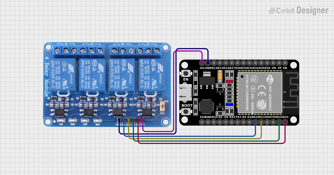
This circuit connects an ESP32 microcontroller to a 4-channel 5V relay module. The ESP32's digital pins (D19, D21, D22, D23) are used to control the relay channels (IN1, IN2, IN3, IN4) respectively. The circuit is designed to allow the ESP32 to switch external devices on and off via the relay module.
ESP32-Based Smart Home Automation System with PIR Motion Sensor and Relay Control
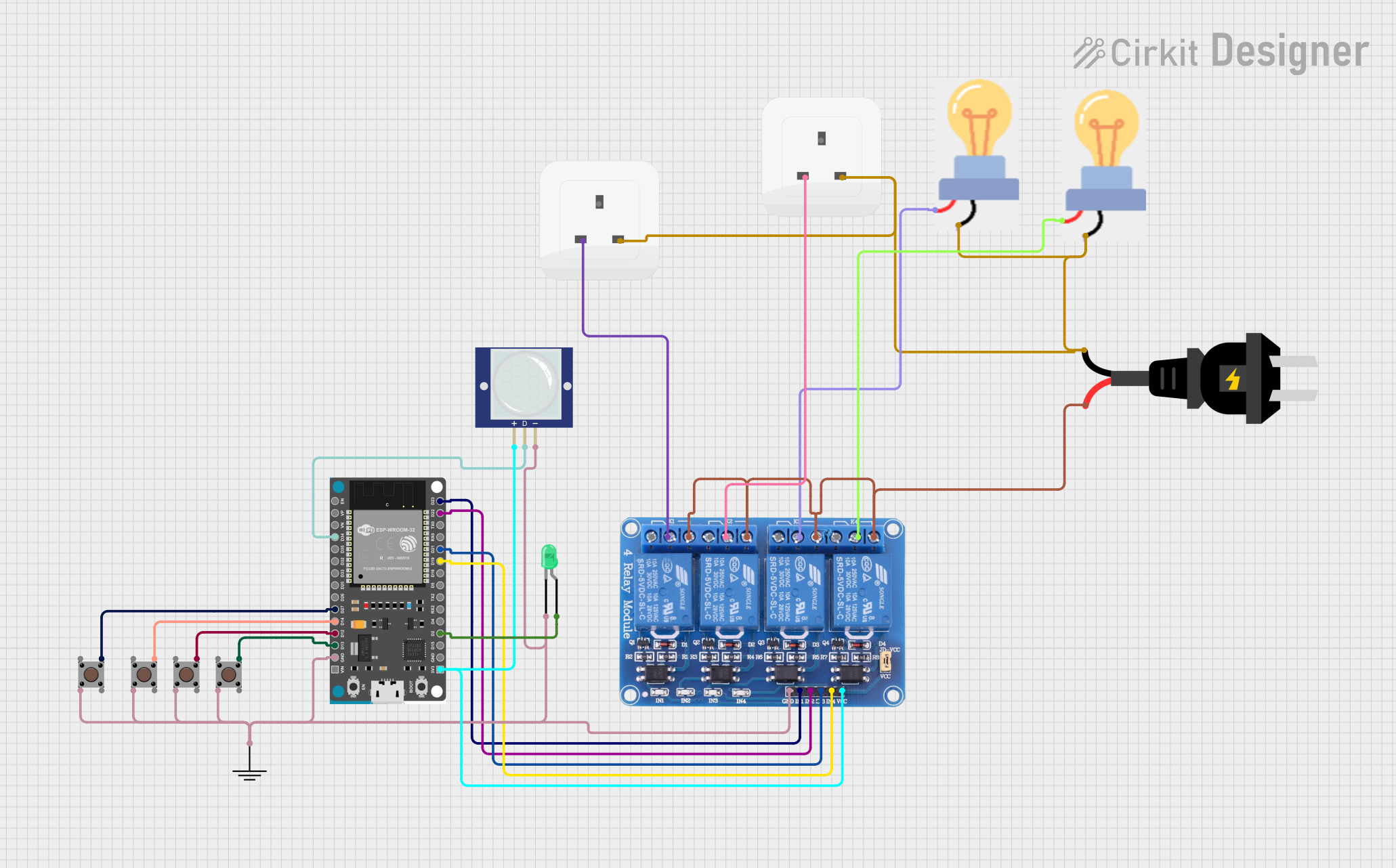
This circuit uses an ESP32 microcontroller to control a 4-channel relay module, which in turn controls two bulbs and two sockets. The circuit also includes a PIR motion sensor and multiple pushbuttons for input, as well as an LED for visual feedback.
ESP32-Controlled Smart Relay System with Motion Detection and Manual Override
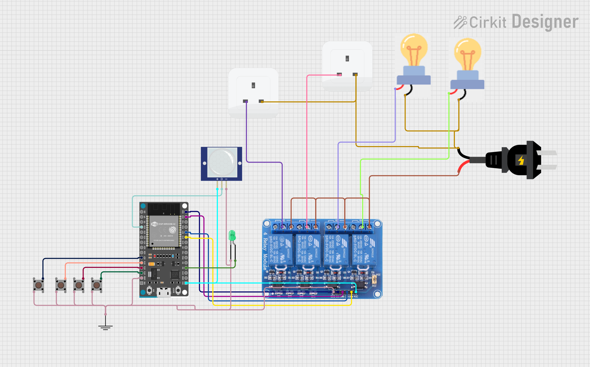
This circuit features an ESP32 Devkit V1 microcontroller connected to a 4-channel 5V relay module, multiple pushbuttons, a PIR motion sensor, and a green LED. The ESP32 controls the relay channels, which in turn can switch AC-powered devices (bulbs) connected via sockets. The pushbuttons and PIR sensor provide input signals to the ESP32, which can be programmed to respond to these inputs by toggling the state of the relays and the LED.
ESP32-Controlled 4-Channel Relay for AC Power Management
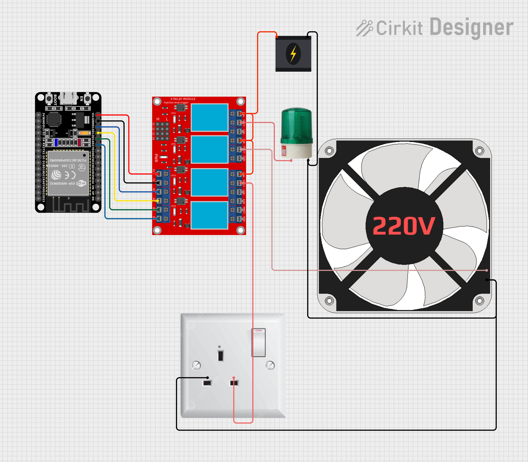
This circuit uses an ESP32 microcontroller to control a 4-channel relay module, which in turn can switch various AC loads. The ESP32's GPIO pins D27, D14, D12, and D13 are connected to the relay module's input channels, allowing the microcontroller to activate the relays. The relay module is used to control the power to a 220V AC fan and a green light, with the potential to control two additional AC loads, all powered by a 240V power source.
Explore Projects Built with ESP32_Relay_X4_V1.1
ESP32-Controlled 4-Channel Relay Module
This circuit connects an ESP32 microcontroller to a 4-channel 5V relay module. The ESP32's digital pins (D19, D21, D22, D23) are used to control the relay channels (IN1, IN2, IN3, IN4) respectively. The circuit is designed to allow the ESP32 to switch external devices on and off via the relay module.
ESP32-Based Smart Home Automation System with PIR Motion Sensor and Relay Control
This circuit uses an ESP32 microcontroller to control a 4-channel relay module, which in turn controls two bulbs and two sockets. The circuit also includes a PIR motion sensor and multiple pushbuttons for input, as well as an LED for visual feedback.
ESP32-Controlled Smart Relay System with Motion Detection and Manual Override
This circuit features an ESP32 Devkit V1 microcontroller connected to a 4-channel 5V relay module, multiple pushbuttons, a PIR motion sensor, and a green LED. The ESP32 controls the relay channels, which in turn can switch AC-powered devices (bulbs) connected via sockets. The pushbuttons and PIR sensor provide input signals to the ESP32, which can be programmed to respond to these inputs by toggling the state of the relays and the LED.
ESP32-Controlled 4-Channel Relay for AC Power Management
This circuit uses an ESP32 microcontroller to control a 4-channel relay module, which in turn can switch various AC loads. The ESP32's GPIO pins D27, D14, D12, and D13 are connected to the relay module's input channels, allowing the microcontroller to activate the relays. The relay module is used to control the power to a 220V AC fan and a green light, with the potential to control two additional AC loads, all powered by a 240V power source.
Technical Specifications
Key Technical Details
| Parameter | Value |
|---|---|
| Microcontroller | ESP32 |
| Number of Relays | 4 |
| Relay Voltage | 5V DC |
| Relay Current | 10A @ 250V AC / 10A @ 30V DC |
| Wi-Fi Standard | 802.11 b/g/n |
| Bluetooth Standard | Bluetooth v4.2 BR/EDR and BLE |
| Operating Voltage | 5V DC |
| Power Consumption | < 500mA |
| Dimensions | 100mm x 70mm x 20mm |
Pin Configuration and Descriptions
| Pin Number | Pin Name | Description |
|---|---|---|
| 1 | VCC | Power supply (5V DC) |
| 2 | GND | Ground |
| 3 | IN1 | Control signal for Relay 1 |
| 4 | IN2 | Control signal for Relay 2 |
| 5 | IN3 | Control signal for Relay 3 |
| 6 | IN4 | Control signal for Relay 4 |
| 7 | TX | UART Transmit |
| 8 | RX | UART Receive |
| 9 | GPIO0 | General Purpose Input/Output 0 |
| 10 | GPIO2 | General Purpose Input/Output 2 |
| 11 | EN | Enable pin for ESP32 |
| 12 | 3V3 | 3.3V output from ESP32 |
Usage Instructions
How to Use the Component in a Circuit
- Power Supply: Connect the VCC pin to a 5V DC power source and the GND pin to the ground.
- Relay Control: Connect the IN1, IN2, IN3, and IN4 pins to the GPIO pins of the ESP32 or any other microcontroller to control the relays.
- Communication: Use the TX and RX pins for UART communication if needed.
- GPIO: Utilize the GPIO0 and GPIO2 pins for additional input/output functionalities.
- Enable Pin: Connect the EN pin to the 3.3V output to enable the ESP32.
Important Considerations and Best Practices
- Isolation: Ensure proper isolation between the high-power relay contacts and the low-power control circuitry to prevent damage.
- Power Supply: Use a stable 5V DC power supply to avoid voltage fluctuations that could affect the ESP32's performance.
- Heat Dissipation: Provide adequate ventilation or heat sinks if the relays are switching high currents frequently.
- Debouncing: Implement software debouncing for the control signals to avoid false triggering of the relays.
Sample Code for Arduino UNO
#include <WiFi.h>

// Define relay control pins
#define RELAY1  5
#define RELAY2  18
#define RELAY3  19
#define RELAY4  21

// Wi-Fi credentials
const char* ssid = "your_SSID";
const char* password = "your_PASSWORD";

void setup() {
  // Initialize serial communication
  Serial.begin(115200);

  // Initialize relay control pins as outputs
  pinMode(RELAY1, OUTPUT);
  pinMode(RELAY2, OUTPUT);
  pinMode(RELAY3, OUTPUT);
  pinMode(RELAY4, OUTPUT);

  // Connect to Wi-Fi
  WiFi.begin(ssid, password);
  while (WiFi.status() != WL_CONNECTED) {
    delay(1000);
    Serial.println("Connecting to WiFi...");
  }
  Serial.println("Connected to WiFi");
}

void loop() {
  // Example: Turn on Relay 1 and Relay 2
  digitalWrite(RELAY1, HIGH);
  digitalWrite(RELAY2, HIGH);
  delay(5000); // Keep relays on for 5 seconds

  // Example: Turn off Relay 1 and Relay 2
  digitalWrite(RELAY1, LOW);
  digitalWrite(RELAY2, LOW);
  delay(5000); // Keep relays off for 5 seconds
}
Troubleshooting and FAQs
Common Issues Users Might Face
ESP32 Not Connecting to Wi-Fi:
- Solution: Double-check the SSID and password. Ensure the Wi-Fi network is operational and within range.
Relays Not Switching:
- Solution: Verify the control signals are correctly connected and the GPIO pins are configured as outputs.
Power Supply Issues:
- Solution: Ensure a stable 5V DC power supply. Check for loose connections or faulty power sources.
Overheating:
- Solution: Provide adequate ventilation or use heat sinks if the relays are frequently switching high currents.
Solutions and Tips for Troubleshooting
- Check Connections: Ensure all connections are secure and correctly wired.
- Use Multimeter: Use a multimeter to check voltage levels and continuity.
- Firmware Update: Ensure the ESP32 firmware is up-to-date.
- Debugging: Use serial print statements to debug and monitor the ESP32's status.
By following this documentation, users can effectively utilize the ESP32_Relay_X4_V1.1 module for various applications, ensuring reliable and efficient control of high-power devices.