How to Use Motor Driver Expansion Board Complete: Examples, Pinouts, and Specs
Introduction
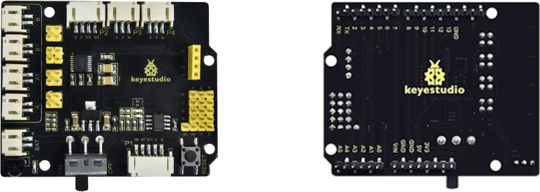
The Keyestudio 8833 Motor Driver Expansion Board is a versatile and powerful module designed to drive motors with ease and efficiency. This board is commonly used in robotics, automation, and various DIY projects where precise motor control is required. It is compatible with platforms like Arduino UNO, making it a popular choice for hobbyists and educators alike.
Explore Projects Built with Motor Driver Expansion Board Complete
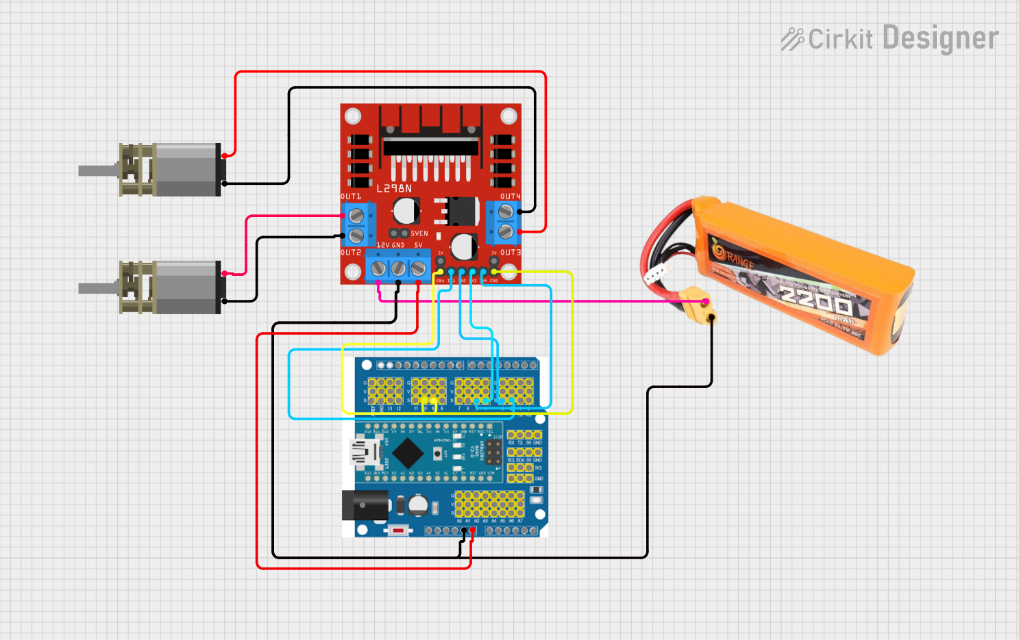
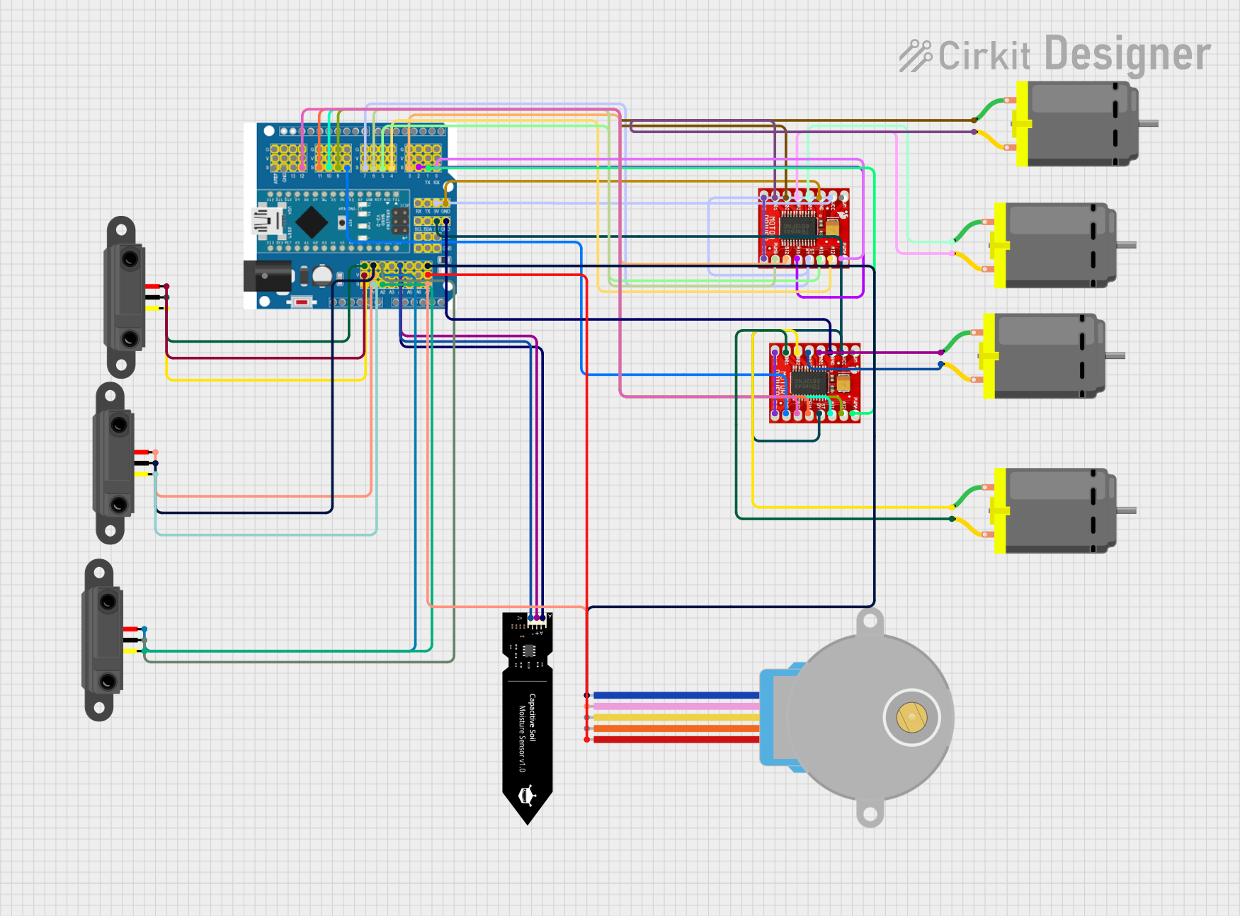
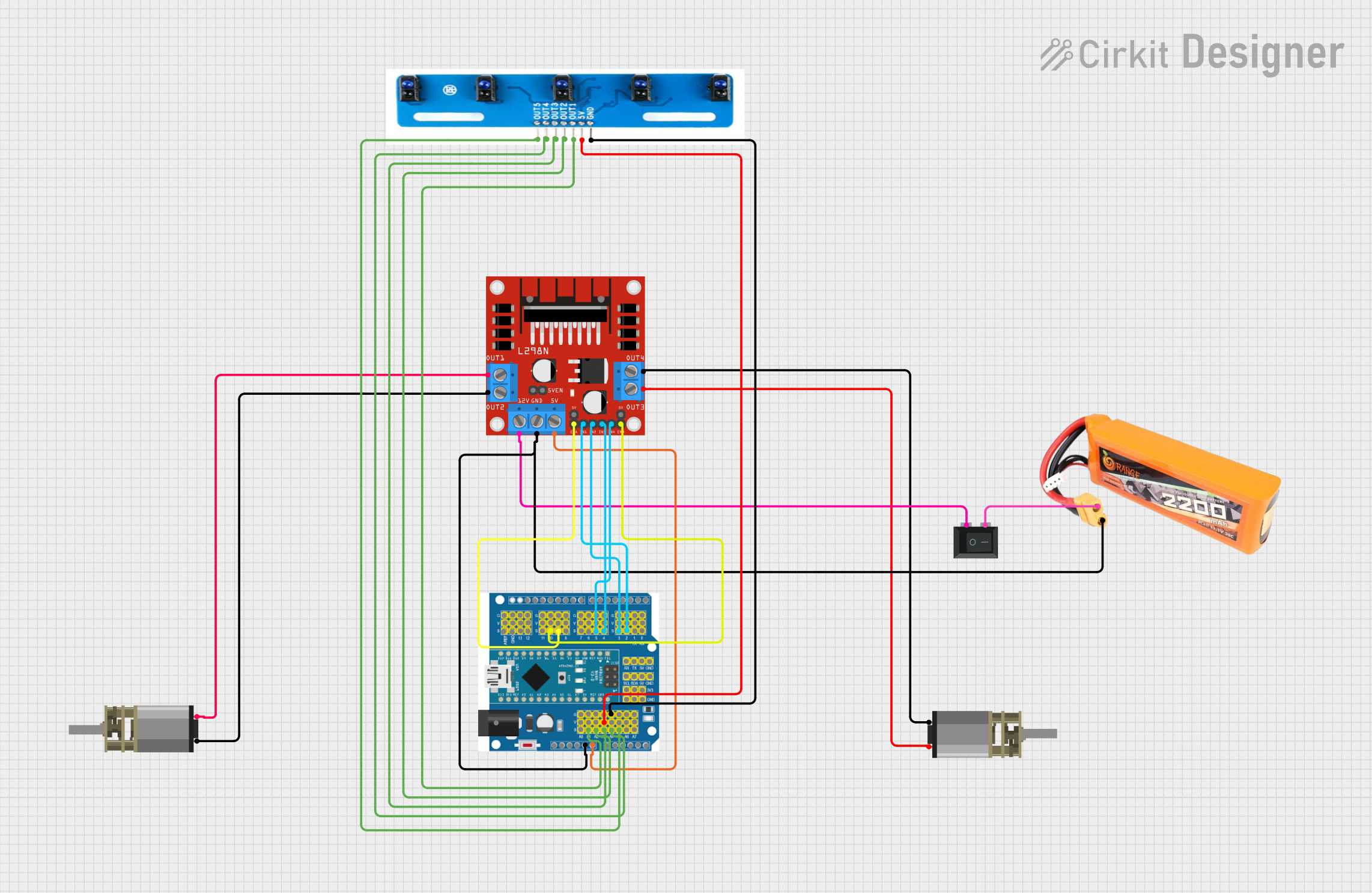

Explore Projects Built with Motor Driver Expansion Board Complete
Common Applications and Use Cases
- Robotics
- Automated machinery
- Educational projects
- Hobbyist DIY projects
- Prototyping motor-driven systems
Technical Specifications
Key Technical Details
- Operating Voltage: 6V to 12V
- Motor Controller: L298P, capable of driving two DC motors or one stepper motor
- Output Current: Up to 2A per channel
- Peak Current: 3A
- Logic Control Voltage: 5V (from Arduino UNO)
- PWM Control: Available for speed regulation
- Protection: Over-temperature, over-current protection
Pin Configuration and Descriptions
| Pin | Function | Description |
|---|---|---|
| M1A | Motor 1 Output A | Connect to one terminal of the first DC motor |
| M1B | Motor 1 Output B | Connect to the other terminal of the first DC motor |
| M2A | Motor 2 Output A | Connect to one terminal of the second DC motor |
| M2B | Motor 2 Output B | Connect to the other terminal of the second DC motor |
| 5V | Power Supply | Provides 5V output (when 7V-12V input is applied) |
| GND | Ground | Common ground for logic and power |
| IN1 | Input 1 | Control signal for Motor 1 (HIGH/LOW) |
| IN2 | Input 2 | Control signal for Motor 1 (HIGH/LOW) |
| IN3 | Input 3 | Control signal for Motor 2 (HIGH/LOW) |
| IN4 | Input 4 | Control signal for Motor 2 (HIGH/LOW) |
| ENA | Enable A | PWM input for speed control of Motor 1 |
| ENB | Enable B | PWM input for speed control of Motor 2 |
Usage Instructions
How to Use the Component in a Circuit
- Power Supply: Connect a 6V to 12V power supply to the board's power input terminals.
- Motor Connections: Attach the motors to the M1 and M2 output terminals.
- Control Signals: Connect the IN1, IN2, IN3, and IN4 pins to the digital outputs of the Arduino UNO.
- PWM Speed Control: Connect the ENA and ENB pins to PWM-capable pins on the Arduino UNO for speed control.
- Logic Power: Ensure the Arduino UNO is powered to provide the 5V logic control voltage.
Important Considerations and Best Practices
- Do not exceed the recommended voltage and current ratings to prevent damage.
- Use a separate power supply for the motors to avoid noise and power issues on the Arduino UNO.
- Always double-check wiring before powering up to prevent shorts and component damage.
- Implement proper cooling if operating near the peak current ratings for extended periods.
Troubleshooting and FAQs
Common Issues
- Motor not running: Check power supply, wiring, and control signals.
- Overheating: Ensure adequate cooling and that the current does not exceed the peak ratings.
- Inconsistent motor speed: Verify PWM signals and connections.
Solutions and Tips for Troubleshooting
- Check Connections: Loose or incorrect connections are often the cause of issues.
- Power Supply: Verify that the power supply is within the specified range and capable of delivering sufficient current.
- Code Review: Ensure that the control logic in the code is correct and that the correct pins are being used.
FAQs
Q: Can I drive a stepper motor with this board? A: Yes, the board can drive one stepper motor using the M1 and M2 outputs.
Q: What is the maximum current the board can handle? A: The board can handle up to 2A per channel continuously, with a peak of 3A.
Q: Can I control the speed of the motors? A: Yes, by applying PWM signals to the ENA and ENB pins, you can control the speed of the motors.
Example Code for Arduino UNO
// Define motor control and PWM pins
const int motor1Pin1 = 3; // IN1 on the Motor Driver
const int motor1Pin2 = 4; // IN2 on the Motor Driver
const int enableMotor1 = 9; // ENA on the Motor Driver

void setup() {
  // Set motor control pins as outputs
  pinMode(motor1Pin1, OUTPUT);
  pinMode(motor1Pin2, OUTPUT);
  pinMode(enableMotor1, OUTPUT);
}

void loop() {
  // Spin motor in one direction
  digitalWrite(motor1Pin1, HIGH);
  digitalWrite(motor1Pin2, LOW);
  analogWrite(enableMotor1, 255); // Full speed
  delay(2000);

  // Stop motor
  digitalWrite(motor1Pin1, LOW);
  digitalWrite(motor1Pin2, LOW);
  delay(1000);

  // Spin motor in the opposite direction
  digitalWrite(motor1Pin1, LOW);
  digitalWrite(motor1Pin2, HIGH);
  analogWrite(enableMotor1, 128); // Half speed
  delay(2000);

  // Stop motor
  digitalWrite(motor1Pin1, LOW);
  digitalWrite(motor1Pin2, LOW);
  delay(1000);
}
Note: The above code is a simple demonstration of controlling a DC motor with the Keyestudio 8833 Motor Driver Expansion Board. Adjust the analogWrite value between 0 (off) and 255 (full speed) to control the motor speed.