How to Use XL4015: Examples, Pinouts, and Specs
Introduction
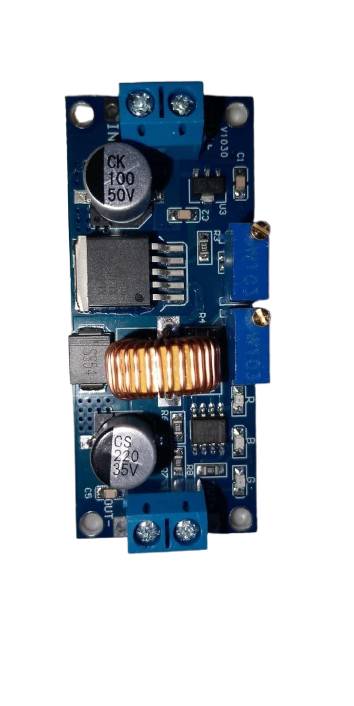
The XL4015 is a high-performance step-down (buck) DC-DC converter designed to efficiently convert a higher input voltage to a lower output voltage. It is capable of delivering up to 5A of output current and features an adjustable output voltage, making it a versatile component for a wide range of applications. Its high efficiency and compact design make it ideal for use in battery charging, LED drivers, and power supplies for electronic devices.
Explore Projects Built with XL4015


Explore Projects Built with XL4015
Common Applications
- Battery charging circuits
- LED drivers
- Power supplies for microcontrollers and other electronic devices
- Voltage regulation in embedded systems
- Solar power systems
Technical Specifications
The XL4015 is a robust and efficient DC-DC converter with the following key specifications:
| Parameter | Value |
|---|---|
| Input Voltage Range | 4V to 38V |
| Output Voltage Range | 1.25V to 36V (adjustable) |
| Maximum Output Current | 5A |
| Output Power | Up to 75W |
| Efficiency | Up to 96% |
| Switching Frequency | 180 kHz |
| Operating Temperature | -40°C to +85°C |
| Dimensions | 51mm x 26mm x 14mm |
Pin Configuration and Descriptions
The XL4015 module typically has the following pinout:
| Pin Name | Description |
|---|---|
| VIN | Input voltage pin. Connect the higher input voltage (4V to 38V) to this pin. |
| VOUT | Output voltage pin. Provides the regulated output voltage (1.25V to 36V). |
| GND | Ground pin. Connect to the ground of the circuit. |
| ADJ | Voltage adjustment pin. Use a potentiometer to set the desired output voltage. |
Usage Instructions
How to Use the XL4015 in a Circuit
Connect the Input Voltage (VIN):
- Connect the positive terminal of the input power source to the VIN pin.
- Connect the negative terminal of the input power source to the GND pin.
Set the Output Voltage:
- Use the onboard potentiometer to adjust the output voltage.
- Turn the potentiometer clockwise to increase the output voltage and counterclockwise to decrease it.
- Use a multimeter to measure the output voltage at the VOUT pin while adjusting.
Connect the Load:
- Connect the positive terminal of the load to the VOUT pin.
- Connect the negative terminal of the load to the GND pin.
Verify Connections:
- Double-check all connections to ensure proper polarity and secure connections.
Power On:
- Turn on the input power source and verify the output voltage and current.
Important Considerations and Best Practices
- Heat Dissipation: The XL4015 can generate heat during operation, especially at high currents. Use a heatsink or active cooling if necessary.
- Input Voltage: Ensure the input voltage is at least 1.5V higher than the desired output voltage for proper regulation.
- Current Limitation: Do not exceed the maximum output current of 5A to avoid damaging the module.
- Capacitors: Use appropriate input and output capacitors to ensure stable operation and reduce voltage ripple.
Example: Using XL4015 with Arduino UNO
The XL4015 can be used to power an Arduino UNO by stepping down a higher voltage (e.g., 12V) to 5V. Below is an example circuit and code:
Circuit Connections
- Connect a 12V power source to the VIN and GND pins of the XL4015.
- Adjust the output voltage to 5V using the potentiometer.
- Connect the VOUT pin of the XL4015 to the 5V pin of the Arduino UNO.
- Connect the GND pin of the XL4015 to the GND pin of the Arduino UNO.
Example Code
// Example code to blink an LED using Arduino UNO powered by XL4015
// Ensure the XL4015 output is set to 5V before connecting to Arduino

const int ledPin = 13; // Built-in LED pin on Arduino UNO

void setup() {
  pinMode(ledPin, OUTPUT); // Set LED pin as output
}

void loop() {
  digitalWrite(ledPin, HIGH); // Turn the LED on
  delay(1000);                // Wait for 1 second
  digitalWrite(ledPin, LOW);  // Turn the LED off
  delay(1000);                // Wait for 1 second
}
Troubleshooting and FAQs
Common Issues and Solutions
No Output Voltage:
- Cause: Incorrect input connections or insufficient input voltage.
- Solution: Verify the input voltage is within the specified range (4V to 38V) and check the polarity of the connections.
Output Voltage Not Adjustable:
- Cause: Faulty potentiometer or incorrect adjustment.
- Solution: Ensure the potentiometer is functioning correctly and adjust it slowly while monitoring the output voltage.
Overheating:
- Cause: High output current or insufficient cooling.
- Solution: Use a heatsink or active cooling to dissipate heat. Reduce the load current if necessary.
Voltage Ripple or Instability:
- Cause: Insufficient input/output capacitors or poor connections.
- Solution: Add appropriate capacitors (e.g., 100µF electrolytic) to the input and output terminals. Ensure all connections are secure.
FAQs
Q1: Can the XL4015 be used to charge batteries?
Yes, the XL4015 can be used for battery charging applications. However, ensure the output voltage and current are set according to the battery's specifications.
Q2: What is the efficiency of the XL4015?
The XL4015 has an efficiency of up to 96%, depending on the input voltage, output voltage, and load conditions.
Q3: Can the XL4015 step up voltage?
No, the XL4015 is a step-down (buck) converter and cannot increase the input voltage.
Q4: Is the XL4015 protected against short circuits?
The XL4015 includes overcurrent and thermal protection, but it is recommended to avoid short circuits to prevent damage.
Q5: Can I use the XL4015 with a solar panel?
Yes, the XL4015 can be used with a solar panel to regulate the output voltage for powering devices or charging batteries. Ensure the input voltage is within the specified range.