
How to Use IP2326 2S LX LSCV2: Examples, Pinouts, and Specs
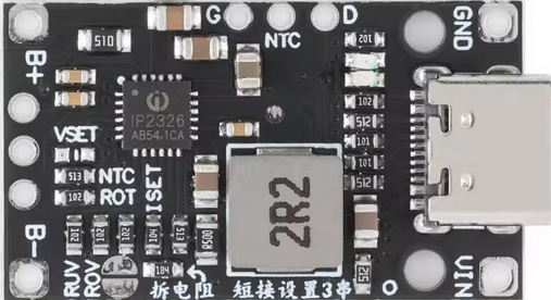
 Design with IP2326 2S LX LSCV2 in Cirkit Designer
Introduction
The IP2326 2S LX LSCV2 is a highly efficient lithium-ion battery protection integrated circuit (IC) designed for 2-cell (2S) battery packs. It provides overcharge, over-discharge, overcurrent, and short-circuit protection to ensure the safety and longevity of lithium-ion batteries. This IC is commonly used in battery management systems (BMS) for portable electronics, power tools, and other rechargeable battery-powered devices.
Explore Projects Built with IP2326 2S LX LSCV2
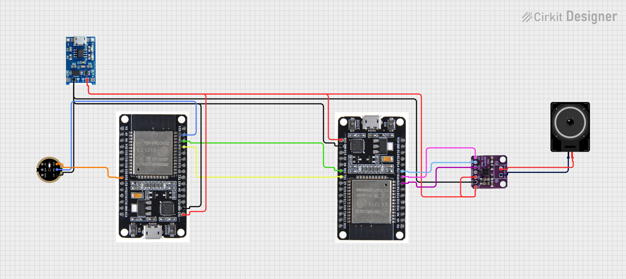 Open Project in Cirkit Designer
 Open Project in Cirkit Designer
 Open Project in Cirkit Designer
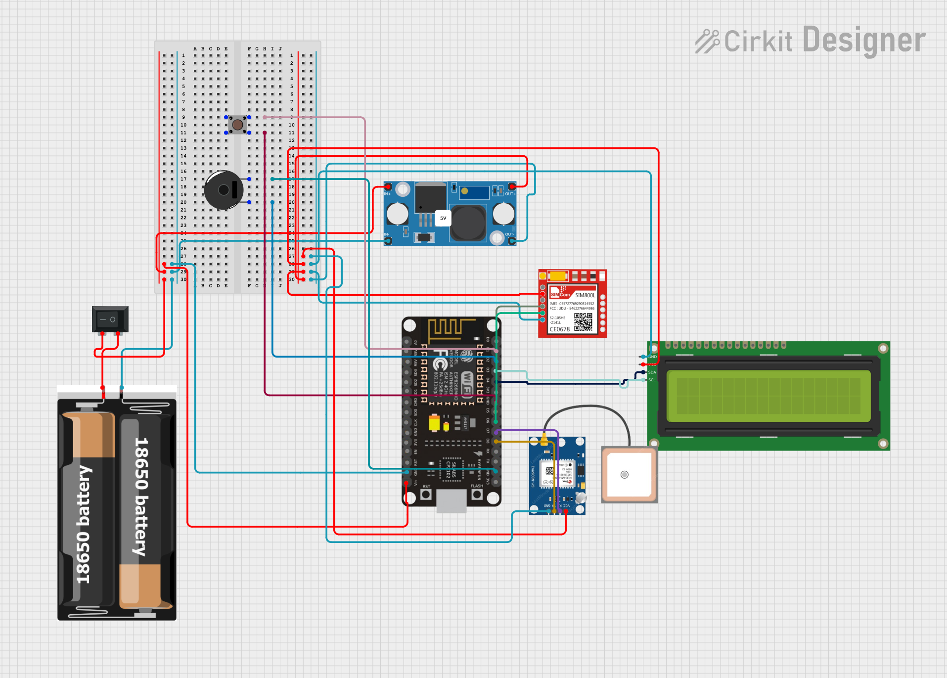 Open Project in Cirkit Designer
Explore Projects Built with IP2326 2S LX LSCV2
Open Project in Cirkit DesignerOpen Project in Cirkit DesignerOpen Project in Cirkit DesignerOpen Project in Cirkit DesignerCommon Applications:
- Lithium-ion battery packs for consumer electronics
- Power tools and cordless devices
- Electric bicycles and scooters
- Backup power systems and uninterruptible power supplies (UPS)
Technical Specifications
The following table outlines the key technical specifications of the IP2326 2S LX LSCV2:
| Parameter | Value |
|---|---|
| Operating Voltage Range | 4.0V to 8.4V |
| Overcharge Detection Voltage | 4.25V ± 0.025V per cell |
| Over-discharge Detection Voltage | 2.5V ± 0.05V per cell |
| Overcurrent Protection | 3A to 6A (configurable) |
| Short-circuit Protection | Triggered at >6A |
| Quiescent Current | ≤ 10 µA |
| Operating Temperature Range | -40°C to +85°C |
Pin Configuration and Descriptions
The IP2326 2S LX LSCV2 IC typically comes in a small SOP-8 package. Below is the pin configuration and description:
| Pin Number | Pin Name | Description |
|---|---|---|
| 1 | VDD | Positive power supply input |
| 2 | VSS | Ground (negative power supply input) |
| 3 | COUT | Overcharge detection output |
| 4 | DOUT | Over-discharge detection output |
| 5 | VM | Voltage monitoring input for cell balancing |
| 6 | V- | Connection to the negative terminal of the battery |
| 7 | V1 | Voltage sense input for the first cell |
| 8 | V2 | Voltage sense input for the second cell |
Usage Instructions
How to Use the IP2326 2S LX LSCV2 in a Circuit
Connect the Battery Pack:
- Connect the positive terminal of the battery pack to the VDD pin.
- Connect the negative terminal of the battery pack to the VSS pin.
- Ensure that the individual cell voltages are connected to the V1 and V2 pins for proper monitoring.
Load and Charging Connections:
- Connect the load to the COUT and DOUT pins for overcharge and over-discharge protection.
- Ensure the charging circuit is connected to the same terminals to allow proper charge management.
Configure Overcurrent Protection:
- Use an external resistor to set the desired overcurrent protection threshold if the IC supports configurable settings.
Cell Balancing:
- If cell balancing is required, connect the VM pin to the appropriate balancing circuit.
Important Considerations and Best Practices
- Voltage Matching: Ensure that the cells in the battery pack are well-matched in terms of capacity and voltage to avoid imbalances.
- Thermal Management: Place the IC in a well-ventilated area or use a heat sink if operating near the upper current limit.
- Avoid Reverse Polarity: Double-check connections to prevent damage to the IC or the battery pack.
- Testing: Test the circuit with a dummy load before connecting to the actual battery pack to verify proper operation.
Example Arduino Code for Monitoring Battery Status
If you are using the IP2326 2S LX LSCV2 with an Arduino UNO to monitor battery status, you can use the following code to read the voltage levels of the two cells:
// Define analog input pins for voltage sensing
const int cell1Pin = A0; // Connect to V1 pin of the IC
const int cell2Pin = A1; // Connect to V2 pin of the IC

void setup() {
  Serial.begin(9600); // Initialize serial communication
}

void loop() {
  // Read the analog voltage levels
  int cell1Raw = analogRead(cell1Pin);
  int cell2Raw = analogRead(cell2Pin);

  // Convert raw ADC values to voltage (assuming 5V reference and 10-bit ADC)
  float cell1Voltage = (cell1Raw / 1023.0) * 5.0 * 2; // Adjust for voltage divider
  float cell2Voltage = (cell2Raw / 1023.0) * 5.0 * 2; // Adjust for voltage divider

  // Print the voltages to the Serial Monitor
  Serial.print("Cell 1 Voltage: ");
  Serial.print(cell1Voltage);
  Serial.println(" V");

  Serial.print("Cell 2 Voltage: ");
  Serial.print(cell2Voltage);
  Serial.println(" V");

  delay(1000); // Wait for 1 second before the next reading
}
Note: Use appropriate voltage dividers to scale down the battery voltage to a safe range for the Arduino's ADC inputs.
Troubleshooting and FAQs
Common Issues
The IC is not providing protection:
- Check all connections, especially the V1 and V2 pins, to ensure proper voltage sensing.
- Verify that the battery pack voltage is within the operating range of the IC.
Overcurrent protection triggers prematurely:
- Ensure the external resistor for overcurrent configuration is correctly selected.
- Check for short circuits or excessive load on the output.
The IC overheats during operation:
- Verify that the load current does not exceed the IC's rated capacity.
- Improve thermal dissipation by adding a heat sink or increasing airflow.
FAQs
Q: Can the IP2326 2S LX LSCV2 be used for 3-cell (3S) battery packs?
A: No, this IC is specifically designed for 2-cell (2S) battery packs. For 3-cell configurations, use an IC designed for 3S applications.
Q: How do I reset the IC after a protection event?
A: Disconnect the load or charger momentarily to reset the IC. Ensure the fault condition is resolved before reconnecting.
Q: Can I use this IC with lithium-polymer (LiPo) batteries?
A: Yes, the IC is compatible with both lithium-ion and lithium-polymer batteries, provided the voltage and current ratings are within the specified range.
This concludes the documentation for the IP2326 2S LX LSCV2.