How to Use 1N4007 Rectifier Diode: Examples, Pinouts, and Specs

Introduction
The 1N4007 is a silicon rectifier diode designed for general-purpose applications. It is capable of withstanding a maximum reverse voltage of 1000V and can handle a forward current of up to 1A. This diode is widely used in power supply circuits for converting alternating current (AC) to direct current (DC). Its robust design and high voltage rating make it suitable for a variety of electronic projects, including rectification, voltage blocking, and polarity protection.
Explore Projects Built with 1N4007 Rectifier Diode
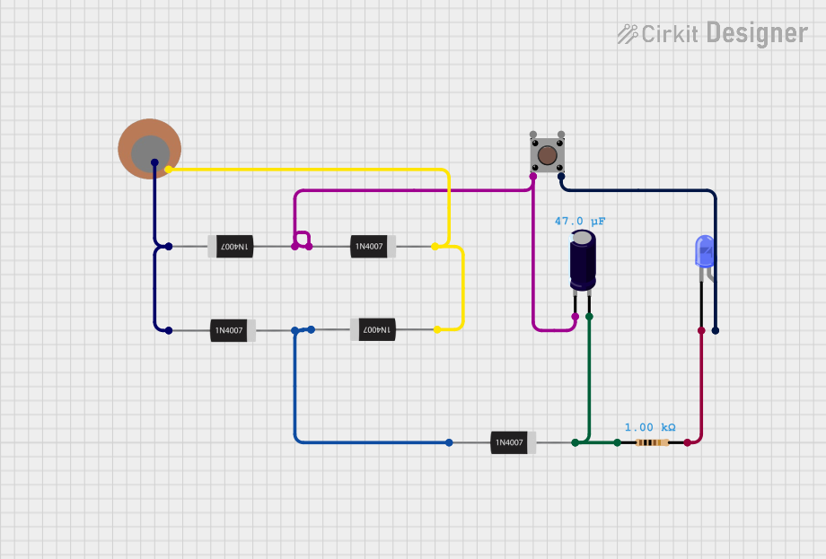
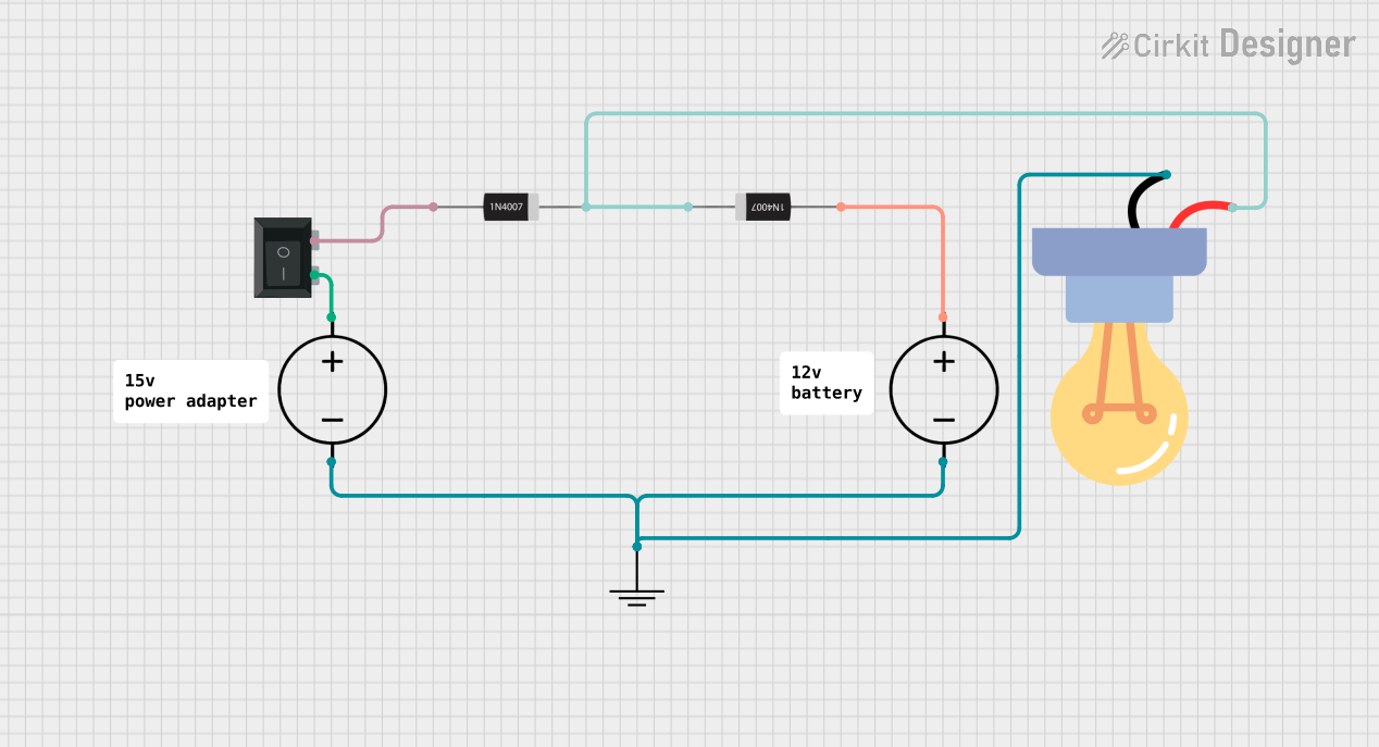
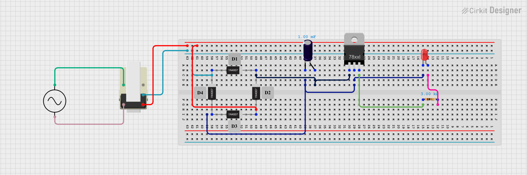

Explore Projects Built with 1N4007 Rectifier Diode
Common Applications:
- AC to DC rectification in power supplies
- Voltage blocking in circuits
- Polarity protection for sensitive components
- Freewheeling diode in inductive loads (e.g., motors, relays)
Technical Specifications
Below are the key technical details of the 1N4007 rectifier diode:
| Parameter | Value |
|---|---|
| Maximum Reverse Voltage | 1000V |
| Maximum Forward Current | 1A |
| Peak Surge Current | 30A (8.3ms single half-sine) |
| Forward Voltage Drop | 1.1V (at 1A) |
| Reverse Current | 5µA (at 25°C) |
| Operating Temperature | -55°C to +150°C |
| Package Type | DO-41 |
Pin Configuration:
The 1N4007 diode has two terminals:
| Pin | Description |
|---|---|
| Anode | Positive terminal (current enters) |
| Cathode | Negative terminal (current exits) |
The cathode is marked with a silver or white band on the diode body.
Usage Instructions
How to Use the 1N4007 in a Circuit:
- Identify the Terminals: Locate the cathode (marked with a silver/white band) and the anode.
- Connect in the Correct Orientation:
- For rectification, connect the anode to the AC source and the cathode to the positive side of the load.
- Ensure the diode is oriented correctly to allow current flow in the desired direction.
- Use in a Rectifier Circuit:
- For a half-wave rectifier, connect the diode in series with the load.
- For a full-wave rectifier, use four 1N4007 diodes in a bridge configuration.
- Add a Filter Capacitor (if needed): To smooth the rectified DC output, connect a capacitor in parallel with the load.
Important Considerations:
- Voltage Rating: Ensure the reverse voltage in your circuit does not exceed 1000V.
- Current Rating: Do not exceed the maximum forward current of 1A to avoid overheating.
- Heat Dissipation: If the diode operates near its maximum ratings, consider adding a heatsink or ensuring proper ventilation.
- Polarity: Incorrect polarity can damage the diode or the circuit.
Example: Using 1N4007 with Arduino UNO
The 1N4007 can be used to protect an Arduino UNO from reverse polarity. Below is an example circuit and code:
Circuit:
- Connect the anode of the 1N4007 to the positive terminal of the power supply.
- Connect the cathode to the VIN pin of the Arduino UNO.
- Connect the negative terminal of the power supply to the GND pin of the Arduino.
Code:
// Example code to blink an LED connected to Arduino UNO
// This demonstrates the use of a 1N4007 diode for reverse polarity protection

const int ledPin = 13; // Pin connected to the onboard LED

void setup() {
  pinMode(ledPin, OUTPUT); // Set the LED pin as an output
}

void loop() {
  digitalWrite(ledPin, HIGH); // Turn the LED on
  delay(1000);                // Wait for 1 second
  digitalWrite(ledPin, LOW);  // Turn the LED off
  delay(1000);                // Wait for 1 second
}
Troubleshooting and FAQs
Common Issues:
Diode Overheating:
- Cause: Exceeding the maximum forward current or reverse voltage.
- Solution: Ensure the diode is operating within its specified ratings. Use a heatsink if necessary.
No Current Flow:
- Cause: Incorrect orientation of the diode.
- Solution: Verify the anode and cathode connections. The cathode should face the load.
Circuit Not Working as Expected:
- Cause: Faulty or damaged diode.
- Solution: Test the diode with a multimeter. Replace if it shows an open or short circuit.
FAQs:
Q1: Can I use the 1N4007 for high-frequency applications?
A1: No, the 1N4007 is not suitable for high-frequency applications due to its slow recovery time. Use a fast recovery or Schottky diode instead.
Q2: What is the difference between the 1N4007 and other diodes in the 1N400x series?
A2: The primary difference is the maximum reverse voltage rating. The 1N4007 has the highest rating (1000V) in the series.
Q3: Can I use the 1N4007 for AC voltage higher than 1000V?
A3: No, the 1N4007 is rated for a maximum reverse voltage of 1000V. Exceeding this limit may damage the diode.
By following this documentation, you can effectively use the 1N4007 rectifier diode in your electronic projects.