How to Use OLED SSD1309 : Examples, Pinouts, and Specs
Introduction
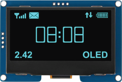
The OLED SSD1309 is a versatile display driver designed for small OLED screens. Manufactured by AITRIP with the part ID 12864 4 Pin IIC I2C, this component is ideal for applications requiring high-contrast graphical or textual displays. It supports resolutions up to 128x64 pixels and operates with low power consumption, making it suitable for battery-powered and embedded systems.
Explore Projects Built with OLED SSD1309
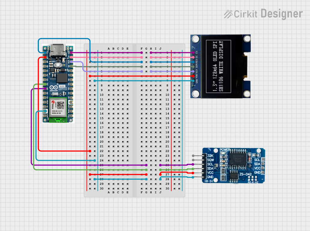


Explore Projects Built with OLED SSD1309
Common Applications
- Wearable devices
- IoT displays
- Portable instrumentation
- Home automation interfaces
- Industrial control panels
Technical Specifications
Key Technical Details
| Parameter | Value |
|---|---|
| Manufacturer | AITRIP |
| Part ID | 12864 4 Pin IIC I2C |
| Display Resolution | 128x64 pixels |
| Interface | I2C (Inter-Integrated Circuit) |
| Operating Voltage | 3.3V to 5V |
| Operating Current | ~20mA |
| Communication Address | 0x3C (default) |
| Display Type | Monochrome OLED |
| Driver IC | SSD1309 |
| Operating Temperature | -40°C to +85°C |
Pin Configuration
The OLED SSD1309 module has a 4-pin interface for I2C communication. Below is the pinout:
| Pin Number | Pin Name | Description |
|---|---|---|
| 1 | GND | Ground (0V) |
| 2 | VCC | Power Supply (3.3V or 5V) |
| 3 | SCL | I2C Clock Line |
| 4 | SDA | I2C Data Line |
Usage Instructions
Connecting the OLED SSD1309 to an Arduino UNO
To use the OLED SSD1309 with an Arduino UNO, follow these steps:
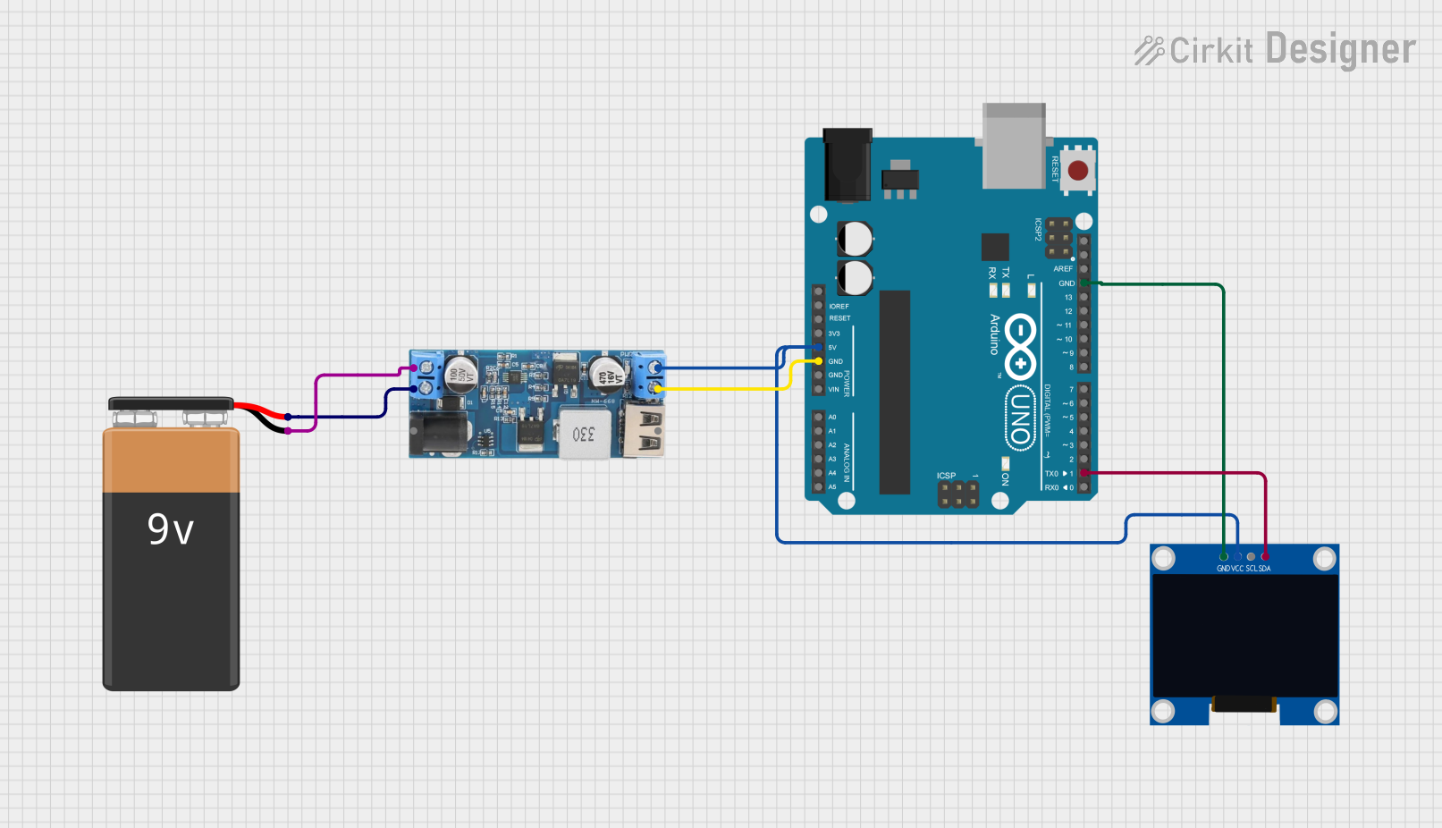
Wiring:
- Connect the GND pin of the OLED to the GND pin of the Arduino.
- Connect the VCC pin of the OLED to the 5V pin of the Arduino.
- Connect the SCL pin of the OLED to the A5 pin of the Arduino (I2C clock line).
- Connect the SDA pin of the OLED to the A4 pin of the Arduino (I2C data line).
Install Required Libraries:
- Install the
Adafruit_GFXandAdafruit_SSD1306libraries from the Arduino Library Manager.
- Install the
Example Code: Use the following code to display text on the OLED:
#include <Wire.h>
#include <Adafruit_GFX.h>
#include <Adafruit_SSD1306.h>

// Define the OLED display width and height
#define SCREEN_WIDTH 128
#define SCREEN_HEIGHT 64

// Create an SSD1306 display object
Adafruit_SSD1306 display(SCREEN_WIDTH, SCREEN_HEIGHT, &Wire, -1);

void setup() {
  // Initialize the display
  if (!display.begin(SSD1306_I2C_ADDRESS, 0x3C)) {
    // If initialization fails, print an error message
    Serial.println(F("SSD1309 initialization failed!"));
    for (;;); // Halt execution
  }

  // Clear the display buffer
  display.clearDisplay();

  // Set text size and color
  display.setTextSize(1); // Small text size
  display.setTextColor(SSD1306_WHITE);

  // Display a message
  display.setCursor(0, 0); // Set cursor to top-left corner
  display.println(F("Hello, SSD1309!"));
  display.display(); // Render the text on the screen
}

void loop() {
  // Nothing to do here
}
Important Considerations
- Ensure the I2C address of the OLED (default:
0x3C) matches the address in your code. - Use pull-up resistors (typically 4.7kΩ) on the SCL and SDA lines if your circuit requires them.
- Avoid exceeding the operating voltage range (3.3V to 5V) to prevent damage to the module.
Troubleshooting and FAQs
Common Issues and Solutions
The display does not turn on:
- Verify the wiring connections, especially the power (VCC and GND) and I2C lines (SCL and SDA).
- Ensure the OLED is receiving the correct voltage (3.3V or 5V).
- Check if the I2C address in the code matches the OLED's default address (
0x3C).
The display shows random or garbled data:
- Confirm that the correct libraries (
Adafruit_GFXandAdafruit_SSD1306) are installed and up to date. - Ensure the I2C clock speed is compatible with the OLED (typically 100kHz or 400kHz).
- Confirm that the correct libraries (
The display remains blank after uploading the code:
- Double-check the initialization code (
display.begin()) and ensure the correct I2C address is used. - Test the I2C connection using an I2C scanner sketch to detect the OLED's address.
- Double-check the initialization code (
The text or graphics appear distorted:
- Verify the resolution settings in the code (
SCREEN_WIDTHandSCREEN_HEIGHT). - Ensure the display buffer is cleared before rendering new content (
display.clearDisplay()).
- Verify the resolution settings in the code (
FAQs
Q: Can I use the OLED SSD1309 with a 3.3V microcontroller?
A: Yes, the OLED SSD1309 is compatible with both 3.3V and 5V logic levels.
Q: What is the maximum I2C cable length for this module?
A: The maximum cable length depends on the pull-up resistor values and the I2C clock speed. For typical setups, keep the cable length under 50cm to ensure reliable communication.
Q: Can I use this module with other microcontrollers like ESP32 or Raspberry Pi?
A: Yes, the OLED SSD1309 is compatible with any microcontroller that supports I2C communication, including ESP32, ESP8266, and Raspberry Pi.
Q: How do I display custom graphics on the OLED?
A: Use the Adafruit_GFX library's functions, such as drawBitmap(), to render custom graphics. You can create bitmaps using online tools or image-to-bitmap converters.
By following this documentation, you can effectively integrate the OLED SSD1309 into your projects and troubleshoot common issues with ease.