Cirkit Designer
Your all-in-one circuit design IDE
Home /
Component Documentation
How to Use 24 V DC Solenoid Valve NC: Examples, Pinouts, and Specs
Introduction
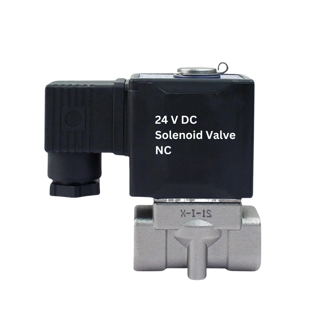
The 24 V DC Solenoid Valve NC (Normally Closed) is an electromechanical device designed to control the flow of fluids. When energized with a 24-volt DC power supply, the valve opens to allow fluid flow. Conversely, when de-energized, the valve closes to stop the flow. This type of solenoid valve is commonly used in various applications, including:
- Automated irrigation systems
- Industrial fluid control
- HVAC systems
- Water treatment plants
- Automotive applications
Explore Projects Built with 24 V DC Solenoid Valve NC
Arduino-Controlled RFM95 Pneumatic Solenoid Valve System
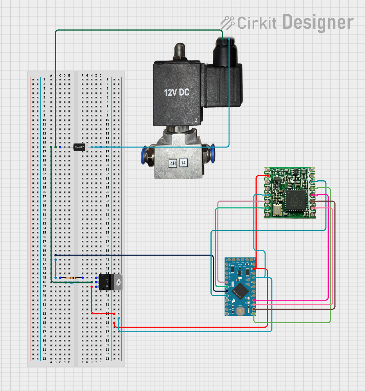
This circuit controls a 12v pneumatic solenoid valve using an Arduino Pro Mini microcontroller. The Arduino toggles the solenoid valve on and off with a 1-second interval, as programmed in the embedded code. A TIP120 Darlington transistor is used to switch the higher current required by the solenoid, and a 1N4007 diode provides back EMF protection. Additionally, an RFM95 module is interfaced with the Arduino for potential wireless communication capabilities.
ESP32-Controlled Water Pump and Solenoid Valve System
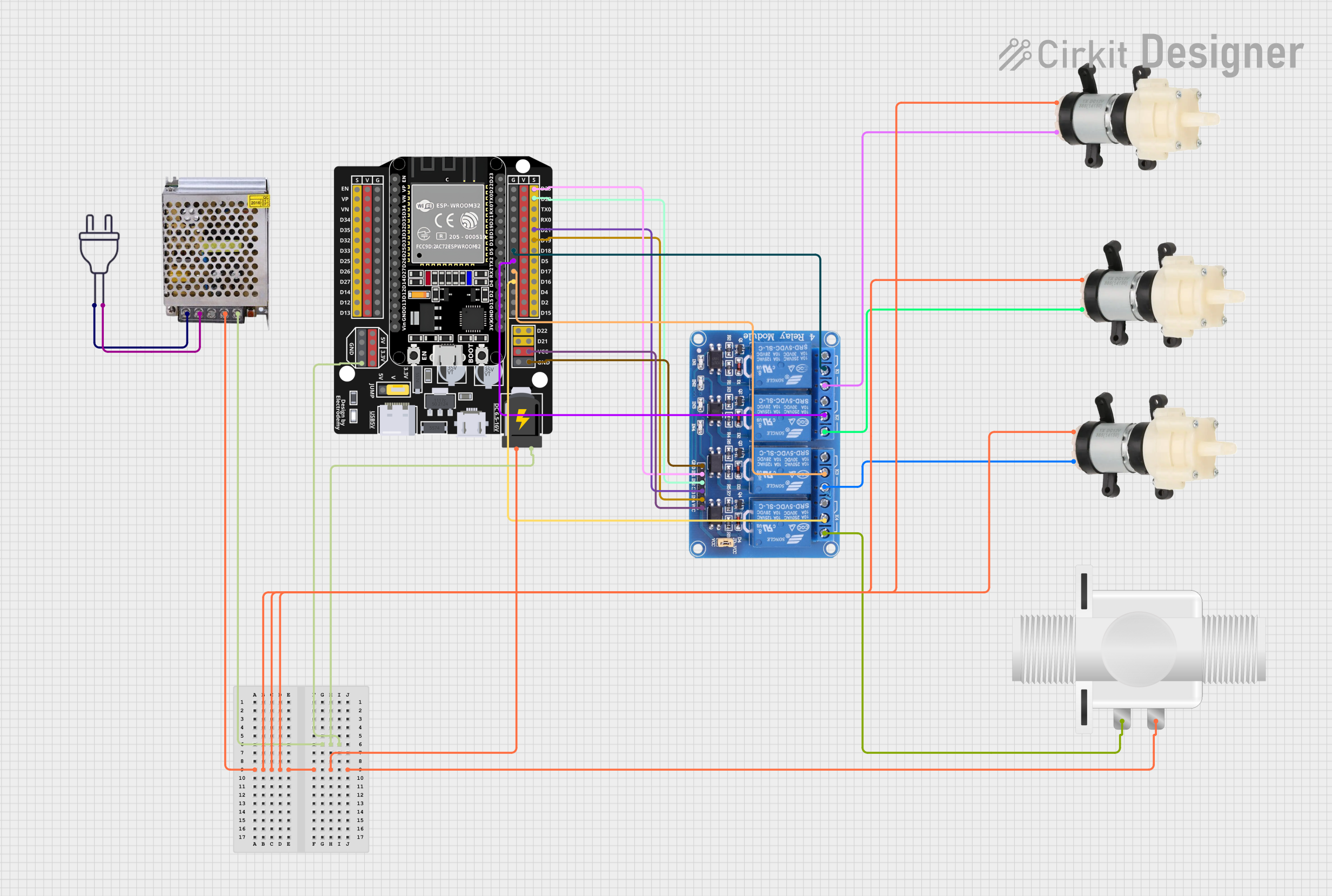
This circuit is designed to control multiple Mini Diaphragm Water Pumps and a Plastic Solenoid Valve using an ESP32 microcontroller and a 4-channel relay module. The ESP32 is powered by a 12V power supply, and it can switch the relays to turn the pumps and the valve on or off. The power supply also provides 220V AC to 12V DC conversion for the system.
Arduino UNO Controlled Relay System with Infrared Proximity Sensors
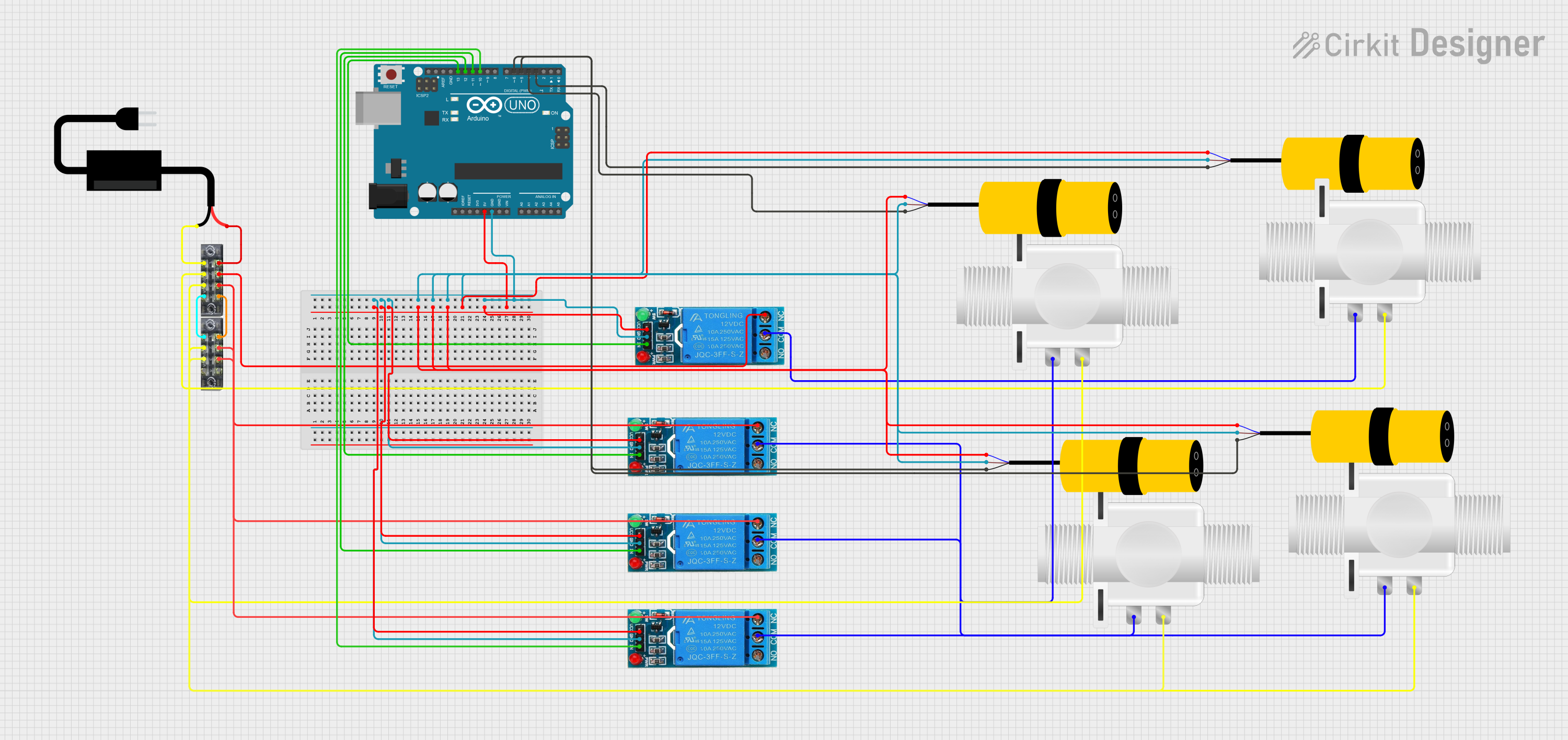
This circuit consists of an Arduino UNO microcontroller interfaced with multiple E18-D80NK infrared proximity sensors and 12V single-channel relays controlling several plastic solenoid valves. The Arduino monitors the sensors and activates the corresponding relays to control the flow through the solenoid valves based on the proximity sensor inputs. A DC power source provides power to the system, with the relays switching the higher voltage lines for the solenoid valves.
Solar-Powered Wi-Fi Water Valve Controller with Battery Backup
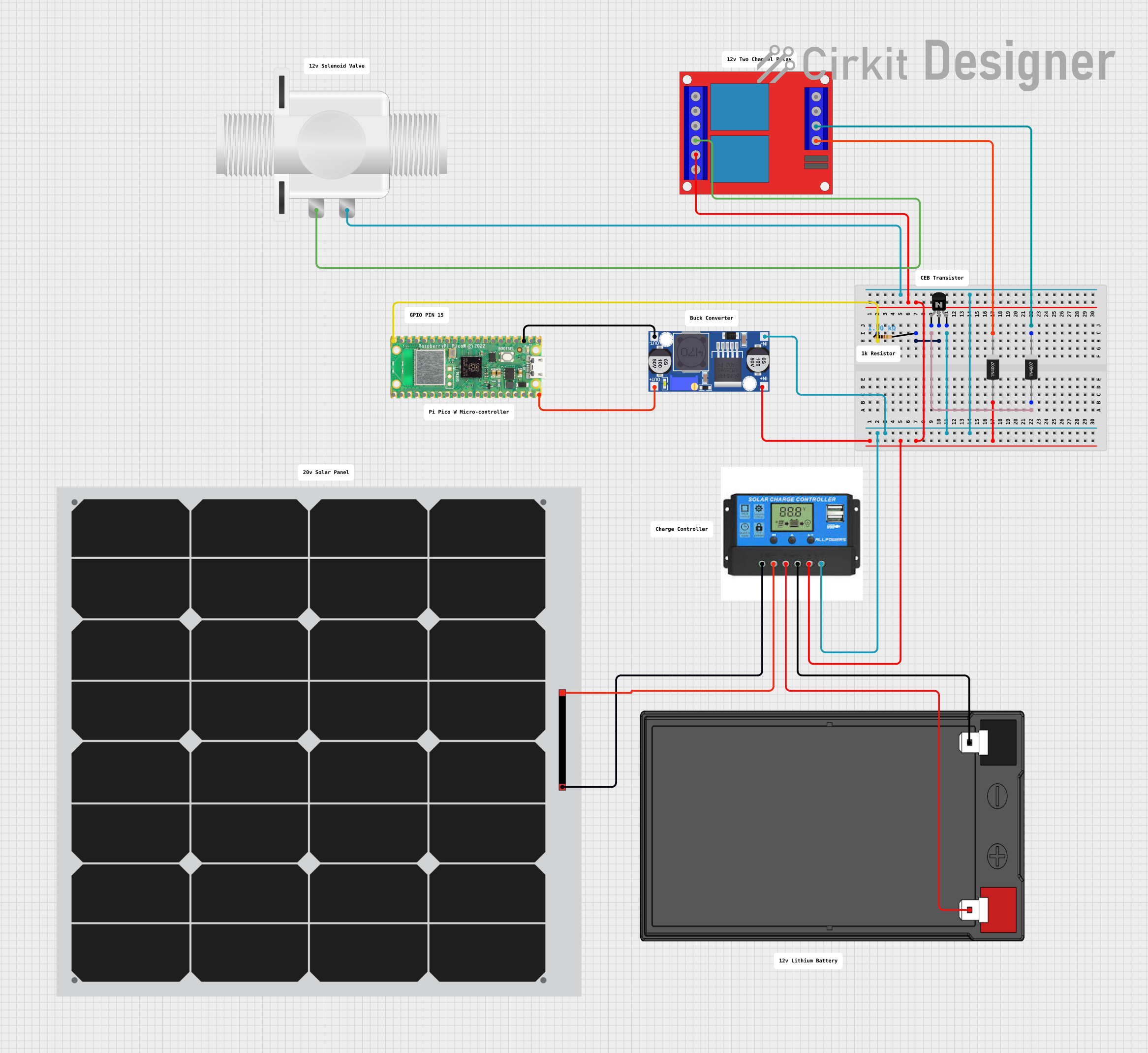
This is a solar-powered control system for a solenoid valve, with a Raspberry Pi Pico W microcontroller managing the valve operation. The system uses a solar panel to charge a battery, which in turn powers the solenoid through a relay, with voltage regulation provided by a buck converter. The Pico W controls the relay via a transistor, and diodes are included for protection against reverse currents.
Explore Projects Built with 24 V DC Solenoid Valve NC
Arduino-Controlled RFM95 Pneumatic Solenoid Valve System
This circuit controls a 12v pneumatic solenoid valve using an Arduino Pro Mini microcontroller. The Arduino toggles the solenoid valve on and off with a 1-second interval, as programmed in the embedded code. A TIP120 Darlington transistor is used to switch the higher current required by the solenoid, and a 1N4007 diode provides back EMF protection. Additionally, an RFM95 module is interfaced with the Arduino for potential wireless communication capabilities.
ESP32-Controlled Water Pump and Solenoid Valve System
This circuit is designed to control multiple Mini Diaphragm Water Pumps and a Plastic Solenoid Valve using an ESP32 microcontroller and a 4-channel relay module. The ESP32 is powered by a 12V power supply, and it can switch the relays to turn the pumps and the valve on or off. The power supply also provides 220V AC to 12V DC conversion for the system.
Arduino UNO Controlled Relay System with Infrared Proximity Sensors
This circuit consists of an Arduino UNO microcontroller interfaced with multiple E18-D80NK infrared proximity sensors and 12V single-channel relays controlling several plastic solenoid valves. The Arduino monitors the sensors and activates the corresponding relays to control the flow through the solenoid valves based on the proximity sensor inputs. A DC power source provides power to the system, with the relays switching the higher voltage lines for the solenoid valves.
Solar-Powered Wi-Fi Water Valve Controller with Battery Backup
This is a solar-powered control system for a solenoid valve, with a Raspberry Pi Pico W microcontroller managing the valve operation. The system uses a solar panel to charge a battery, which in turn powers the solenoid through a relay, with voltage regulation provided by a buck converter. The Pico W controls the relay via a transistor, and diodes are included for protection against reverse currents.
Technical Specifications
Key Technical Details
| Parameter | Value |
|---|---|
| Operating Voltage | 24 V DC |
| Current Rating | 0.5 A |
| Power Consumption | 12 W |
| Operating Pressure | 0-10 bar |
| Response Time | < 50 ms |
| Port Size | 1/2 inch |
| Material | Brass/Stainless Steel |
| Temperature Range | -10°C to 80°C |
Pin Configuration and Descriptions
| Pin Number | Description |
|---|---|
| 1 | Positive Terminal (+) |
| 2 | Negative Terminal (-) |
Usage Instructions
How to Use the Component in a Circuit
- Power Supply: Connect the positive terminal of a 24 V DC power supply to Pin 1 and the negative terminal to Pin 2.
- Control: Use a switch or a microcontroller (e.g., Arduino UNO) to control the power supply to the solenoid valve.
- Fluid Connections: Connect the inlet and outlet ports to the fluid lines. Ensure that the flow direction matches the arrow on the valve body.
Important Considerations and Best Practices
- Polarity: Ensure correct polarity when connecting the power supply to avoid damage.
- Voltage: Use a regulated 24 V DC power supply to ensure stable operation.
- Environment: Install the valve in a location that is protected from extreme temperatures and moisture.
- Maintenance: Periodically check for debris or blockages in the valve to ensure proper operation.
Example Circuit with Arduino UNO
/*
 * Example code to control a 24 V DC Solenoid Valve NC using Arduino UNO.
 * The solenoid valve is connected to a relay module, which is controlled
 * by the Arduino.
 */

const int relayPin = 7; // Pin connected to the relay module

void setup() {
  pinMode(relayPin, OUTPUT); // Set relay pin as an output
  digitalWrite(relayPin, LOW); // Ensure the relay is off initially
}

void loop() {
  digitalWrite(relayPin, HIGH); // Turn on the relay (energize solenoid)
  delay(5000); // Keep the valve open for 5 seconds
  digitalWrite(relayPin, LOW); // Turn off the relay (de-energize solenoid)
  delay(5000); // Keep the valve closed for 5 seconds
}
Troubleshooting and FAQs
Common Issues Users Might Face
- Valve Not Opening/Closing:
- Solution: Check the power supply voltage and ensure it is 24 V DC. Verify the connections and polarity.
- Fluid Leakage:
- Solution: Ensure that the fluid connections are tight and that the seals are intact. Check for any debris in the valve.
- No Response from Valve:
- Solution: Verify that the control signal (e.g., from Arduino) is correctly reaching the relay module. Check the relay module for proper operation.
Solutions and Tips for Troubleshooting
- Check Connections: Ensure all electrical and fluid connections are secure and correct.
- Measure Voltage: Use a multimeter to measure the voltage at the solenoid terminals to ensure it is 24 V DC.
- Inspect for Damage: Look for any visible signs of damage or wear on the valve and its components.
- Test Relay: If using a relay module, test it separately to ensure it is functioning correctly.
By following this documentation, users can effectively integrate and troubleshoot the 24 V DC Solenoid Valve NC in their projects, ensuring reliable and efficient fluid control.