
How to Use AD8226 Instrumentation Amplifier on DIP Adapter: Examples, Pinouts, and Specs
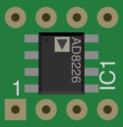
 Design with AD8226 Instrumentation Amplifier on DIP Adapter in Cirkit Designer
Introduction
The AD8226 is a low-power instrumentation amplifier designed for high precision and low noise applications. It is ideal for amplifying small differential signals in the presence of large common-mode voltages. The DIP adapter simplifies the integration of the AD8226 into breadboards and prototyping setups, making it easier to connect the amplifier to various sensors and signal sources.
Explore Projects Built with AD8226 Instrumentation Amplifier on DIP Adapter
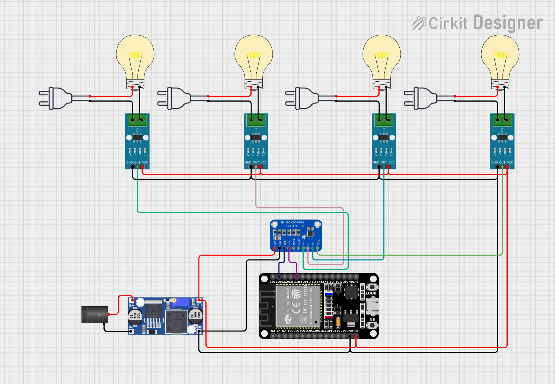 Open Project in Cirkit Designer
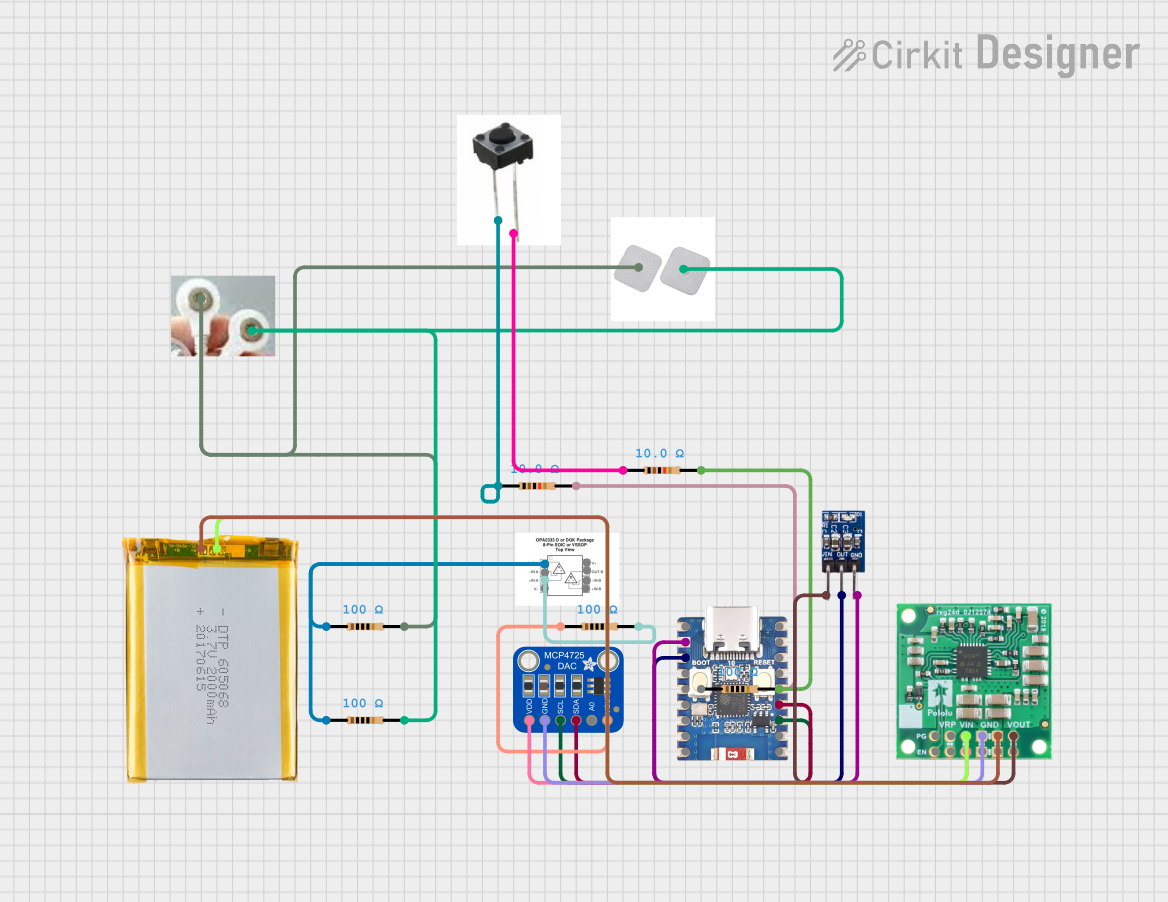 Open Project in Cirkit Designer
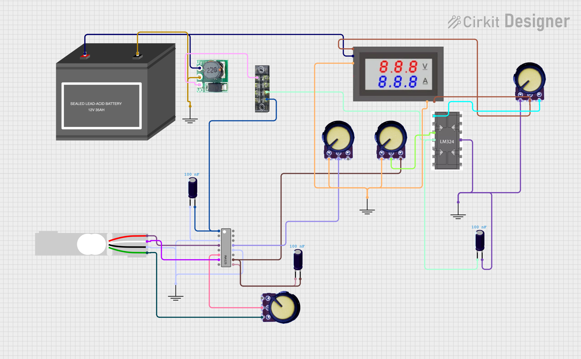 Open Project in Cirkit Designer
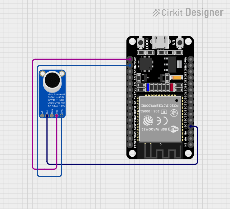 Open Project in Cirkit Designer
Explore Projects Built with AD8226 Instrumentation Amplifier on DIP Adapter
Open Project in Cirkit DesignerOpen Project in Cirkit DesignerOpen Project in Cirkit DesignerOpen Project in Cirkit DesignerCommon Applications
- Medical instrumentation (e.g., ECG, EEG)
- Sensor signal conditioning
- Data acquisition systems
- Industrial process controls
- Strain gauge and bridge amplifiers
Technical Specifications
Key Technical Details
| Parameter | Value |
|---|---|
| Supply Voltage Range | ±2.3 V to ±18 V or 4.6 V to 36 V |
| Input Voltage Range | ±Vs (rail-to-rail input capability) |
| Gain Range | 1 to 1000 (set by external resistor) |
| Gain Error | ±0.3% (maximum) |
| Input Offset Voltage | 125 µV (typical) |
| Input Bias Current | 2 nA (typical) |
| Bandwidth (G = 1) | 1.5 MHz |
| Slew Rate | 0.3 V/µs |
| Output Voltage Swing | Rail-to-rail |
| Quiescent Current | 400 µA (typical) |
| Package Type | DIP adapter for breadboard compatibility |
Pin Configuration and Descriptions
The AD8226 on a DIP adapter has the following pinout:
| Pin Number | Pin Name | Description |
|---|---|---|
| 1 | +IN | Non-inverting input |
| 2 | -IN | Inverting input |
| 3 | RG1 | Gain resistor connection 1 |
| 4 | V- | Negative power supply |
| 5 | REF | Reference voltage input |
| 6 | OUT | Amplifier output |
| 7 | RG2 | Gain resistor connection 2 |
| 8 | V+ | Positive power supply |
Usage Instructions
How to Use the AD8226 in a Circuit
- Power Supply: Connect the
V+pin to a positive voltage source (e.g., +5V) and theV-pin to a negative voltage source (e.g., -5V) or ground for single-supply operation. - Input Connections: Connect the differential signal to the
+INand-INpins. Ensure the input voltage is within the specified range. - Gain Setting: Use an external resistor between the
RG1andRG2pins to set the gain. The gain is calculated as: [ G = 1 + \frac{49.4 , \text{k}\Omega}{R_G} ] where ( R_G ) is the resistance in ohms. - Reference Voltage: Connect the
REFpin to a reference voltage (e.g., ground for single-ended output). - Output: The amplified signal will be available at the
OUTpin.
Important Considerations
- Use precision resistors for ( R_G ) to ensure accurate gain settings.
- Decouple the power supply with capacitors (e.g., 0.1 µF ceramic and 10 µF electrolytic) close to the
V+andV-pins. - Avoid exceeding the input voltage range to prevent damage to the amplifier.
- For optimal performance, ensure proper grounding and minimize noise in the circuit.
Example: Connecting to an Arduino UNO
The AD8226 can be used to amplify a sensor signal for an Arduino UNO. Below is an example of interfacing the AD8226 with a strain gauge sensor:
Circuit Connections
- Connect the strain gauge output to the
+INand-INpins of the AD8226. - Set the gain using a resistor between
RG1andRG2. - Connect the
OUTpin of the AD8226 to an analog input pin (e.g., A0) on the Arduino UNO. - Power the AD8226 with a single supply (e.g., +5V to
V+and GND toV-).
Arduino Code Example
// Define the analog input pin for the AD8226 output
const int analogPin = A0;

void setup() {
  Serial.begin(9600); // Initialize serial communication at 9600 baud
}

void loop() {
  int sensorValue = analogRead(analogPin); // Read the amplified signal
  float voltage = sensorValue * (5.0 / 1023.0); // Convert to voltage
  Serial.print("Amplified Voltage: ");
  Serial.println(voltage); // Print the voltage to the serial monitor
  delay(500); // Wait for 500 ms before the next reading
}
Troubleshooting and FAQs
Common Issues and Solutions
No Output Signal:
- Verify the power supply connections to
V+andV-. - Ensure the input signal is within the specified range.
- Check the gain resistor ( R_G ) for proper value and connection.
- Verify the power supply connections to
Output Signal is Saturated:
- Ensure the input signal is not too large for the configured gain.
- Verify the reference voltage at the
REFpin.
High Noise in Output:
- Use proper decoupling capacitors on the power supply pins.
- Minimize the length of input and output wires to reduce noise pickup.
Incorrect Gain:
- Double-check the value of ( R_G ) and recalculate the gain using the formula.
FAQs
Q: Can the AD8226 operate with a single power supply?
A: Yes, the AD8226 can operate with a single supply. Connect V- to ground and ensure the input and output signals remain within the specified range.
Q: What is the maximum gain I can achieve with the AD8226?
A: The maximum gain is 1000, which can be achieved by using an appropriate ( R_G ) resistor.
Q: Can I use the AD8226 for AC signals?
A: Yes, the AD8226 can amplify AC signals. Ensure proper coupling and biasing for AC applications.
Q: How do I protect the AD8226 from input overvoltage?
A: Use series resistors or clamping diodes to limit the input voltage to within the specified range.