
How to Use Header 2: Examples, Pinouts, and Specs
 Design with Header 2 in Cirkit Designer
Introduction
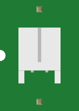
A Header 2 is a type of connector used in electronic circuits to facilitate the connection of multiple wires or components. It typically features two rows of pins, making it ideal for secure and organized connections in compact spaces. Header 2 connectors are widely used in prototyping, PCB designs, and modular systems where reliable and repeatable connections are required.
Explore Projects Built with Header 2
 Open Project in Cirkit Designer
 Open Project in Cirkit Designer
 Open Project in Cirkit Designer
 Open Project in Cirkit Designer
Explore Projects Built with Header 2
Open Project in Cirkit DesignerOpen Project in Cirkit DesignerOpen Project in Cirkit DesignerOpen Project in Cirkit DesignerCommon Applications and Use Cases
- Connecting peripheral devices to microcontrollers or development boards
- Modular PCB designs for easy assembly and disassembly
- Interfacing sensors, displays, or other components in embedded systems
- Creating custom wiring harnesses for electronics projects
Technical Specifications
Key Technical Details
- Number of Pins: Typically ranges from 2x2 (4 pins) to 2x40 (80 pins)
- Pin Pitch: Standard 2.54 mm (0.1 inch) spacing
- Current Rating: Typically 1A to 3A per pin (varies by manufacturer)
- Voltage Rating: Up to 250V (varies by manufacturer)
- Material: Pins are usually made of brass or phosphor bronze with gold or tin plating
- Operating Temperature: -40°C to +105°C (varies by manufacturer)
Pin Configuration and Descriptions
The pin configuration of a Header 2 connector depends on the number of pins and their arrangement. Below is an example of a 2x4 (8-pin) Header 2 connector:
| Pin Number | Description |
|---|---|
| 1 | Signal or Power Line 1 |
| 2 | Signal or Power Line 2 |
| 3 | Signal or Power Line 3 |
| 4 | Signal or Power Line 4 |
| 5 | Ground or Signal Return Line |
| 6 | Ground or Signal Return Line |
| 7 | Signal or Power Line 5 |
| 8 | Signal or Power Line 6 |
Note: The exact pin assignments depend on the specific application and circuit design.
Usage Instructions
How to Use the Component in a Circuit
- Soldering:
- Solder the Header 2 connector onto a PCB, ensuring proper alignment with the board's footprint.
- Use a soldering iron with a fine tip for precision and avoid overheating the pins.
- Connecting Components:
- Insert compatible female connectors, jumper wires, or ribbon cables into the Header 2 pins.
- Ensure a snug fit to maintain a reliable electrical connection.
- Orientation:
- Pay attention to the orientation of the connector to avoid reversed connections.
- Use markings or keying features (if available) to guide proper alignment.
Important Considerations and Best Practices
- Pin Pitch Compatibility: Ensure that the mating connector or cable matches the 2.54 mm pin pitch.
- Current and Voltage Ratings: Do not exceed the specified current and voltage ratings to avoid overheating or damage.
- Mechanical Stress: Avoid applying excessive force when inserting or removing connectors to prevent bending or breaking the pins.
- Plating Material: For high-reliability applications, prefer gold-plated pins to reduce oxidation and improve conductivity.
Example: Using Header 2 with an Arduino UNO
Header 2 connectors are commonly used to interface external components with an Arduino UNO. Below is an example of connecting an 8-pin Header 2 to control an LED array:
Circuit Setup
- Connect the Header 2 pins to the Arduino UNO's digital pins (e.g., D2 to D9).
- Connect the other row of Header 2 pins to the LED array's cathodes and a common ground.
Arduino Code
// Define the pins connected to the Header 2 connector
const int ledPins[] = {2, 3, 4, 5, 6, 7, 8, 9}; // Digital pins D2 to D9

void setup() {
  // Set all pins as outputs
  for (int i = 0; i < 8; i++) {
    pinMode(ledPins[i], OUTPUT);
  }
}

void loop() {
  // Turn LEDs on sequentially
  for (int i = 0; i < 8; i++) {
    digitalWrite(ledPins[i], HIGH); // Turn on LED
    delay(200);                    // Wait for 200ms
    digitalWrite(ledPins[i], LOW); // Turn off LED
  }
}
Note: Ensure that the LEDs are connected with appropriate current-limiting resistors to prevent damage.
Troubleshooting and FAQs
Common Issues Users Might Face
Loose Connections:
- Problem: The connection between the Header 2 and the mating connector is loose.
- Solution: Ensure the mating connector is compatible and properly aligned. Replace worn-out connectors if necessary.
Bent or Broken Pins:
- Problem: Pins are bent or broken due to excessive force or mishandling.
- Solution: Use a small pair of pliers to carefully straighten bent pins. Replace the connector if pins are broken.
Intermittent Connections:
- Problem: Electrical connections are unreliable or intermittent.
- Solution: Clean the pins with isopropyl alcohol to remove dirt or oxidation. Use gold-plated connectors for better reliability.
Overheating During Soldering:
- Problem: Pins or plastic housing melt during soldering.
- Solution: Use a soldering iron with temperature control and limit soldering time to a few seconds per pin.
FAQs
Q: Can I use a Header 2 connector for high-frequency signals?
A: Yes, but ensure the connector's impedance matches the signal requirements to minimize losses.Q: Are Header 2 connectors polarized?
A: Some Header 2 connectors include keying features to prevent incorrect orientation, but not all. Verify the orientation during installation.Q: How do I choose the right number of pins for my project?
A: Determine the number of signals or power lines required and select a Header 2 connector with sufficient pins.Q: Can I use Header 2 connectors in harsh environments?
A: For harsh environments, choose connectors with protective coatings or housings to resist moisture, dust, and corrosion.