How to Use TB6600: Examples, Pinouts, and Specs
Introduction
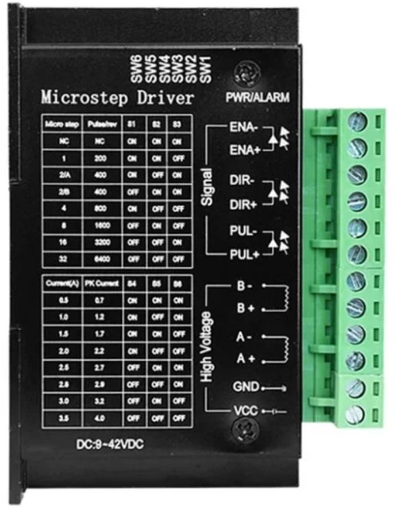
The TB6600 is a high-performance stepper motor driver designed to control bipolar stepper motors with precision and efficiency. It is widely used in applications requiring accurate motor control, such as robotics, CNC machinery, 3D printers, and automated systems. The TB6600 supports adjustable current settings, microstepping capabilities, and includes built-in thermal protection, making it a reliable choice for demanding projects.
Explore Projects Built with TB6600


Explore Projects Built with TB6600
Common Applications
- CNC machines for precise motion control
- Robotics for driving stepper motors in robotic arms or mobile platforms
- 3D printers for controlling the movement of print heads and platforms
- Automated conveyor systems
- DIY projects requiring stepper motor control
Technical Specifications
The TB6600 stepper motor driver offers robust performance and flexibility. Below are its key technical details:
| Parameter | Value |
|---|---|
| Operating Voltage | 9V to 42V DC |
| Output Current | Adjustable, up to 4.5A |
| Microstepping Modes | Full, 1/2, 1/4, 1/8, 1/16 |
| Input Signal Voltage | 3.3V to 24V |
| Control Signals | Pulse (PUL+/-), Direction (DIR+/-), Enable (ENA+/-) |
| Step Frequency Range | 0 to 200 kHz |
| Protection Features | Overheat, overcurrent, and short-circuit protection |
| Dimensions | 96mm x 56mm x 33mm |
Pin Configuration and Descriptions
The TB6600 has a set of input and output terminals for connecting to the motor, power supply, and control signals. Below is the pin configuration:
Input Terminals
| Pin Name | Description |
|---|---|
| PUL+ | Positive terminal for pulse signal input |
| PUL- | Negative terminal for pulse signal input |
| DIR+ | Positive terminal for direction signal input |
| DIR- | Negative terminal for direction signal input |
| ENA+ | Positive terminal for enable signal input (optional) |
| ENA- | Negative terminal for enable signal input (optional) |
Output Terminals
| Pin Name | Description |
|---|---|
| A+ | Positive terminal for motor coil A |
| A- | Negative terminal for motor coil A |
| B+ | Positive terminal for motor coil B |
| B- | Negative terminal for motor coil B |
Power Terminals
| Pin Name | Description |
|---|---|
| VCC | Positive terminal for DC power supply (9V to 42V) |
| GND | Ground terminal for DC power supply |
Usage Instructions
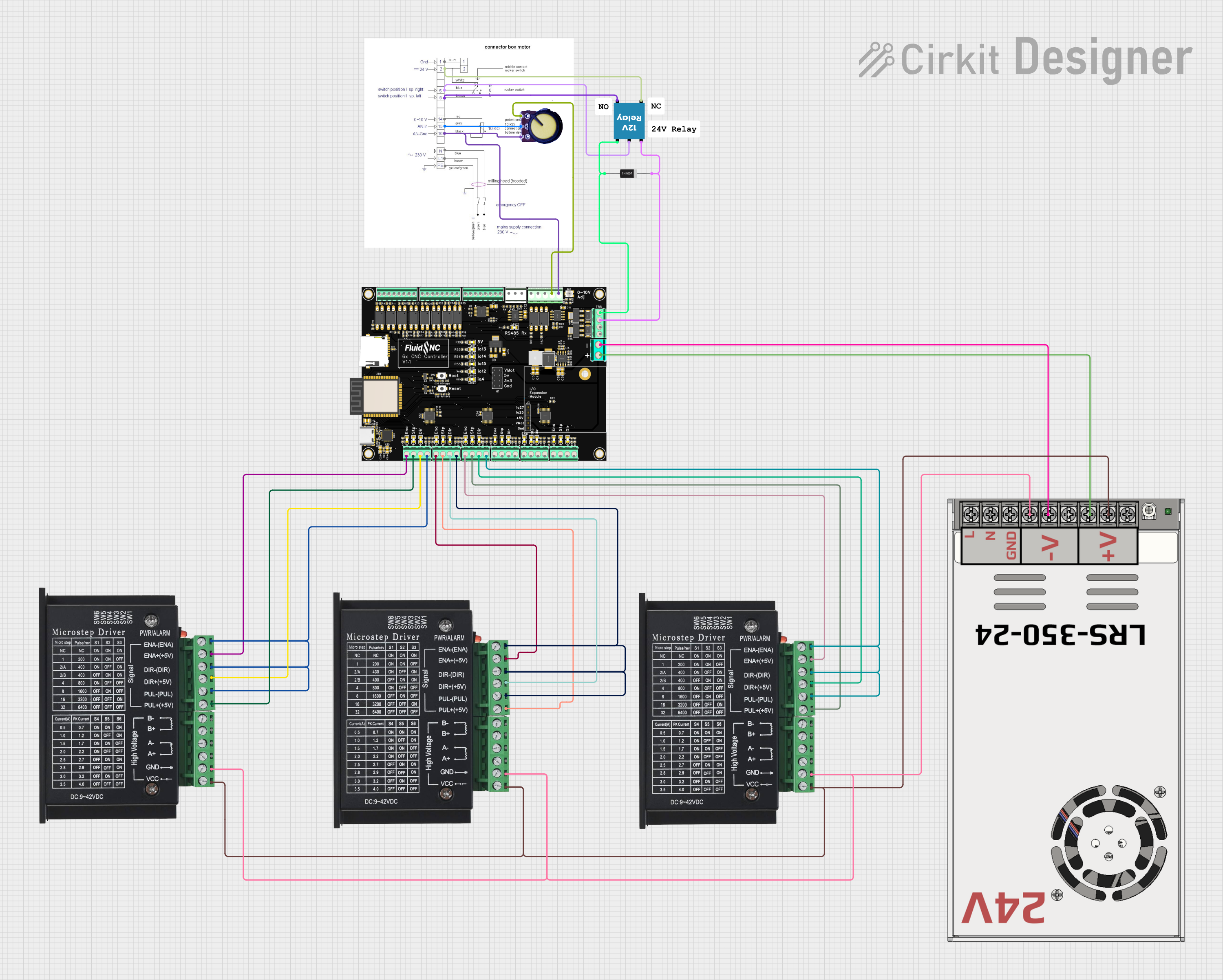
Connecting the TB6600
- Power Supply: Connect a DC power supply (9V to 42V) to the VCC and GND terminals. Ensure the power supply can provide sufficient current for the motor.
- Stepper Motor: Connect the stepper motor's coils to the A+/A- and B+/B- terminals. Refer to the motor's datasheet to identify the correct coil pairs.
- Control Signals: Connect the PUL+/PUL-, DIR+/DIR-, and optionally ENA+/ENA- terminals to a microcontroller or control board (e.g., Arduino UNO).
- Microstepping and Current Settings: Use the DIP switches on the TB6600 to configure the desired microstepping mode and current limit. Refer to the TB6600 datasheet for DIP switch settings.
Example: Using TB6600 with Arduino UNO
Below is an example of how to control a stepper motor using the TB6600 and Arduino UNO:
Circuit Connections
- Connect the TB6600's PUL+, DIR+, and ENA+ to Arduino digital pins 2, 3, and 4, respectively.
- Connect the PUL-, DIR-, and ENA- to Arduino GND.
- Connect the stepper motor and power supply as described above.
Arduino Code
// Define control pins for the TB6600
#define PUL_PIN 2  // Pulse signal pin
#define DIR_PIN 3  // Direction signal pin
#define ENA_PIN 4  // Enable signal pin

void setup() {
  // Set control pins as outputs
  pinMode(PUL_PIN, OUTPUT);
  pinMode(DIR_PIN, OUTPUT);
  pinMode(ENA_PIN, OUTPUT);

  // Enable the driver
  digitalWrite(ENA_PIN, LOW); // LOW enables the driver
}

void loop() {
  // Set direction to clockwise
  digitalWrite(DIR_PIN, HIGH);

  // Generate pulses to move the motor
  for (int i = 0; i < 200; i++) { // 200 steps for one revolution (1.8° step angle)
    digitalWrite(PUL_PIN, HIGH);
    delayMicroseconds(500); // Adjust for speed
    digitalWrite(PUL_PIN, LOW);
    delayMicroseconds(500);
  }

  delay(1000); // Wait for 1 second

  // Set direction to counterclockwise
  digitalWrite(DIR_PIN, LOW);

  // Generate pulses to move the motor in the opposite direction
  for (int i = 0; i < 200; i++) {
    digitalWrite(PUL_PIN, HIGH);
    delayMicroseconds(500);
    digitalWrite(PUL_PIN, LOW);
    delayMicroseconds(500);
  }

  delay(1000); // Wait for 1 second
}
Important Considerations
- Power Supply: Ensure the power supply voltage and current match the requirements of both the TB6600 and the stepper motor.
- Heat Dissipation: The TB6600 can generate heat during operation. Use a heatsink or active cooling if necessary.
- Signal Voltage: Ensure the control signal voltage (3.3V or 5V) is compatible with the TB6600's input range.
Troubleshooting and FAQs
Common Issues
Motor Not Moving:
- Check all connections, especially the motor coils and control signals.
- Verify the power supply voltage and current are sufficient.
- Ensure the enable signal (ENA) is set to LOW.
Motor Vibrates but Does Not Rotate:
- Verify the correct wiring of the motor coils (A+/A-, B+/B-).
- Check the microstepping settings on the DIP switches.
Driver Overheating:
- Ensure proper ventilation or use a heatsink.
- Reduce the current setting using the DIP switches.
Inconsistent Motor Movement:
- Check for noise or interference in the control signals.
- Use shielded cables for long signal connections.
FAQs
Q: Can I use the TB6600 with a unipolar stepper motor?
A: No, the TB6600 is designed for bipolar stepper motors only.
Q: What is the maximum step frequency supported by the TB6600?
A: The TB6600 supports a maximum step frequency of 200 kHz.
Q: How do I set the microstepping mode?
A: Use the DIP switches on the TB6600 to configure the microstepping mode. Refer to the TB6600 datasheet for detailed settings.
Q: Can I control the TB6600 with a 3.3V microcontroller?
A: Yes, the TB6600 supports input signal voltages from 3.3V to 24V, making it compatible with 3.3V microcontrollers like the ESP32.
By following this documentation, you can effectively use the TB6600 stepper motor driver in your projects.