How to Use L6470_AutoDriver_v13: Examples, Pinouts, and Specs
Introduction
The L6470 AutoDriver v13 is a sophisticated stepper motor driver module designed to deliver precise motion control in a variety of applications. It is capable of driving stepper motors by providing full, half, quarter, and microstepping capabilities. This module is particularly useful in applications requiring complex motion patterns, such as 3D printers, CNC machines, robotics, and automated equipment.
Explore Projects Built with L6470_AutoDriver_v13

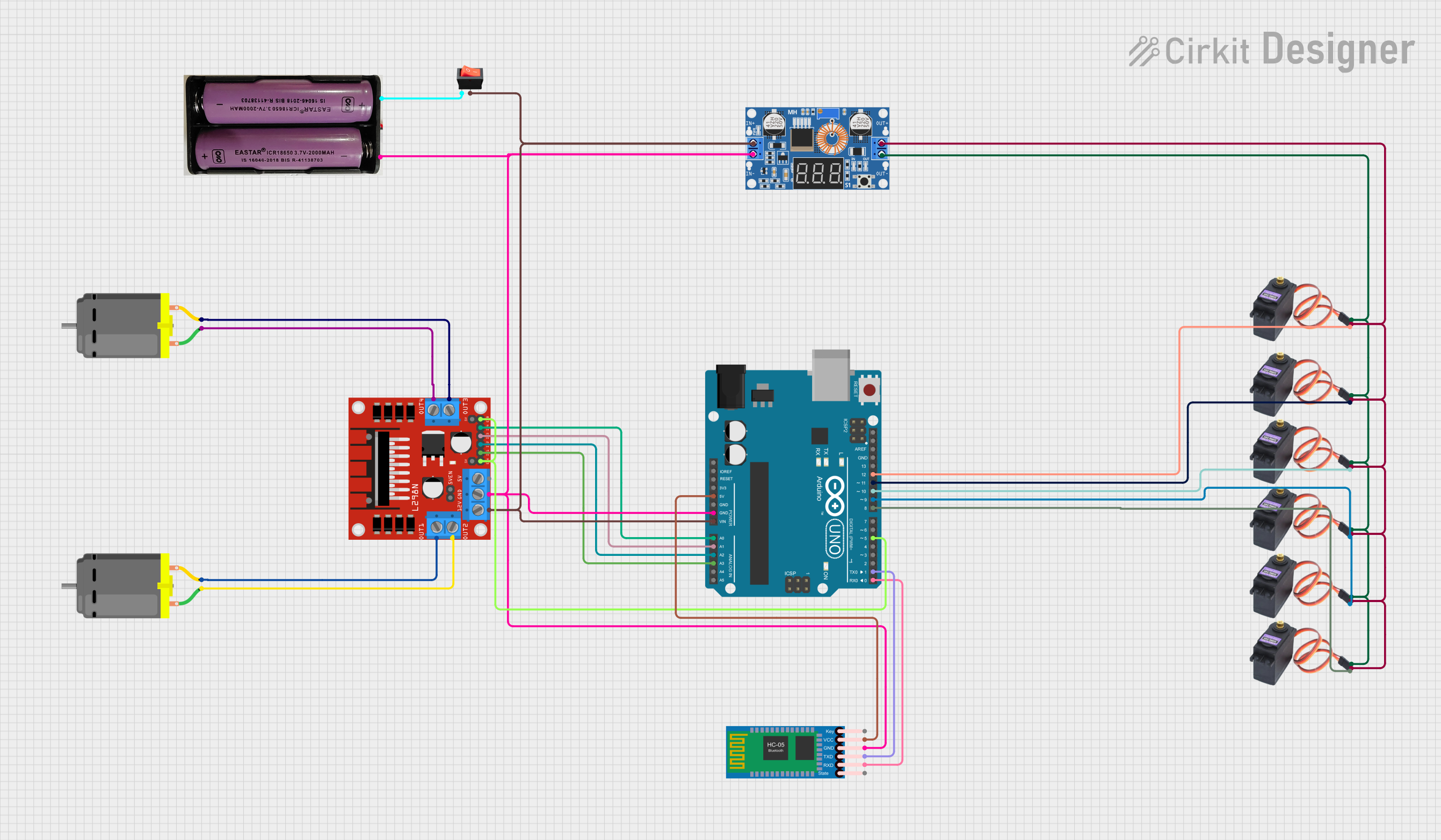

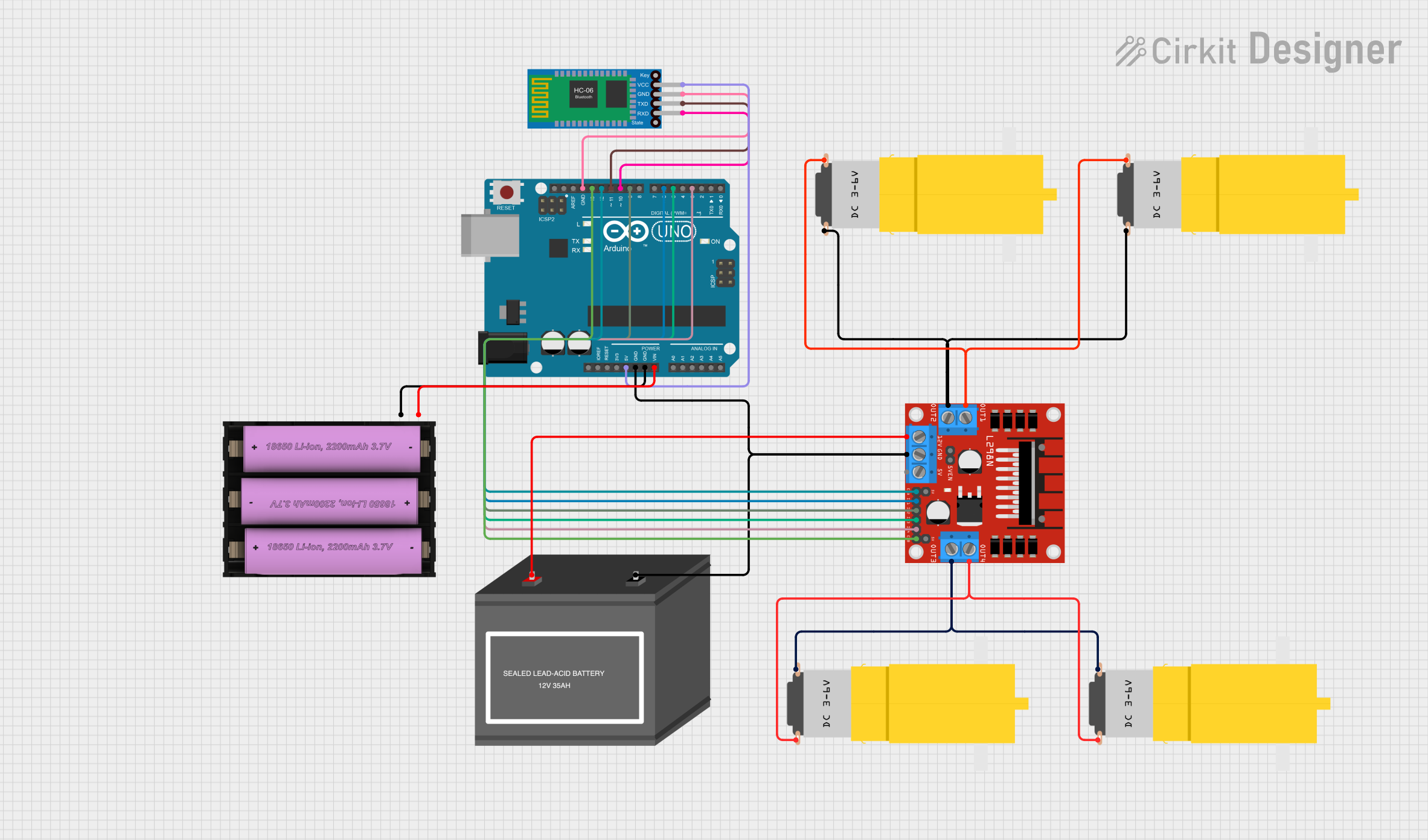
Explore Projects Built with L6470_AutoDriver_v13
Common Applications and Use Cases
- 3D Printing
- CNC Machining
- Robotics
- Precision Positioning Systems
- Automated Assembly Lines
Technical Specifications
Key Technical Details
- Motor Supply Voltage (Min-Max): 8 - 45 V
- Output Current (Max): 2 A per phase
- Step Resolution: Full, Half, 1/4, 1/8, 1/16, 1/32, 1/128, 1/256 microstepping
- Programmable Speed Profile: Yes
- Communication Interface: SPI
- Overcurrent Protection: Yes
- Thermal Shutdown: Yes
- Voltage Regulator: Integrated
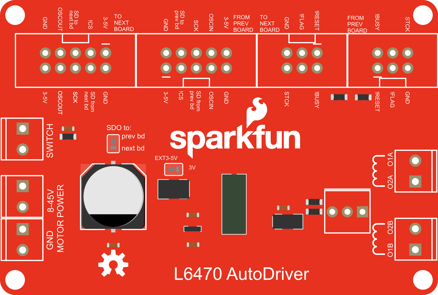
Pin Configuration and Descriptions
| Pin Number | Name | Description |
|---|---|---|
| 1 | VDD | Logic supply voltage (3.3V - 5V) |
| 2 | GND | Ground connection |
| 3 | FLT | Fault flag output (active low) |
| 4 | STCK | Step clock input |
| 5 | SDI | SPI data input |
| 6 | SDO | SPI data output |
| 7 | SCK | SPI clock input |
| 8 | CSN | SPI chip select (active low) |
| 9 | FLAG | Status flag output (active low) |
| 10 | BUSY | Busy flag output (active low) |
| 11-18 | B1A, B1B, A1A, A1B, A2A, A2B, B2A, B2B | Motor coil outputs |
Usage Instructions
How to Use the Component in a Circuit
Power Connections:
- Connect the motor supply voltage (8-45V) to the VM pin.
- Connect the logic supply voltage (3.3V-5V) to the VDD pin.
- Ensure all GND pins are connected to the system ground.
Motor Connections:
- Connect the stepper motor coils to the B1A, B1B, A1A, A1B, A2A, A2B, B2A, and B2B pins according to the motor's datasheet.
SPI Communication:
- Connect the SDI, SDO, SCK, and CSN pins to the corresponding SPI pins on the microcontroller (e.g., Arduino UNO).
Control Inputs:
- Optionally, connect the STCK pin to a digital output on the microcontroller for step clock control.
Important Considerations and Best Practices
- Ensure the power supply can deliver sufficient current for the motor.
- Use proper decoupling capacitors close to the module to minimize voltage spikes.
- Configure the SPI communication correctly, respecting the timing requirements.
- Avoid running the motor at its maximum current rating continuously to prevent overheating.
- Use heat sinks if operating the driver at high currents for extended periods.
Example Code for Arduino UNO
#include <SPI.h>

// Define the SPI parameters
#define CS_PIN 10 // Chip select pin for the L6470

void setup() {
  // Set up the SPI communication
  SPI.begin();
  pinMode(CS_PIN, OUTPUT);
  digitalWrite(CS_PIN, HIGH); // Deselect the L6470
}

void loop() {
  // Example: Send a command to the L6470
  digitalWrite(CS_PIN, LOW); // Select the L6470
  SPI.transfer(0x00); // Send a NOP command to the L6470
  digitalWrite(CS_PIN, HIGH); // Deselect the L6470
}
Troubleshooting and FAQs
Common Issues Users Might Face
- Motor not moving: Check power supply, motor connections, and SPI communication.
- Overheating: Ensure proper current settings and consider adding a heat sink.
- Noise or erratic movement: Adjust the step resolution or check for mechanical obstructions.
Solutions and Tips for Troubleshooting
- Power Supply Issues: Verify the voltage and current ratings of your power supply.
- SPI Communication: Double-check the wiring and ensure the SPI settings match the L6470 requirements.
- Current Settings: Use the L6470 configuration registers to set the appropriate current limits.
FAQs
Q: Can I drive two motors with one L6470 AutoDriver? A: No, the L6470 is designed to drive one stepper motor per module.
Q: What is the maximum step resolution of the L6470? A: The L6470 supports up to 1/256 microstepping.
Q: How do I set the current limit for the motor? A: The current limit is set through the L6470's internal registers, which can be accessed via SPI commands.
Q: What should I do if the L6470 overheats? A: Reduce the current limit, improve ventilation, add a heat sink, or check for mechanical load issues.
This documentation provides a comprehensive guide to the L6470 AutoDriver v13. For further information, consult the manufacturer's datasheet and application notes.