
How to Use TMP01 - Low Power, Programmable Temperature Controller: Examples, Pinouts, and Specs
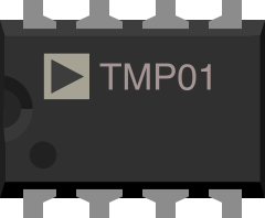
 Design with TMP01 - Low Power, Programmable Temperature Controller in Cirkit Designer
Introduction
The TMP01FPZ, manufactured by Analog Devices, is a low-power, programmable temperature controller designed for precise temperature monitoring and control. It features adjustable temperature set points, making it ideal for applications requiring accurate thermal management. The TMP01 is equipped with dual temperature set points (high and low) and open-collector outputs for temperature threshold signaling. Its low power consumption and ease of integration make it suitable for a wide range of applications.
Explore Projects Built with TMP01 - Low Power, Programmable Temperature Controller
 Open Project in Cirkit Designer
 Open Project in Cirkit Designer
 Open Project in Cirkit Designer
 Open Project in Cirkit Designer
Explore Projects Built with TMP01 - Low Power, Programmable Temperature Controller
Open Project in Cirkit DesignerOpen Project in Cirkit DesignerOpen Project in Cirkit DesignerOpen Project in Cirkit DesignerCommon Applications
- Industrial temperature monitoring and control
- HVAC systems
- Consumer electronics thermal management
- Battery management systems
- Medical devices requiring precise temperature regulation
Technical Specifications
Key Technical Details
| Parameter | Value |
|---|---|
| Supply Voltage (Vcc) | 4.5 V to 13.2 V |
| Supply Current | 500 µA (typical) |
| Temperature Range | -55°C to +150°C |
| Temperature Accuracy | ±1°C (typical) |
| Output Type | Open-collector |
| High/Low Set Point Range | Programmable via external resistors |
| Output Drive Capability | 20 mA (maximum) |
| Package Type | 8-lead PDIP, SOIC, or CERDIP |
Pin Configuration and Descriptions
The TMP01 is an 8-pin device. Below is the pinout and description:
| Pin No. | Pin Name | Description |
|---|---|---|
| 1 | V+ | Positive supply voltage (4.5 V to 13.2 V). |
| 2 | SET HIGH | High-temperature set point input. Connect to a resistor divider network. |
| 3 | SET LOW | Low-temperature set point input. Connect to a resistor divider network. |
| 4 | GND | Ground reference. |
| 5 | OUT HIGH | Open-collector output for high-temperature threshold. |
| 6 | OUT LOW | Open-collector output for low-temperature threshold. |
| 7 | TEMP OUT | Analog voltage output proportional to temperature. |
| 8 | NC | No connection. Leave unconnected or grounded. |
Usage Instructions
How to Use the TMP01 in a Circuit
- Power Supply: Connect the V+ pin to a stable power supply (4.5 V to 13.2 V) and the GND pin to the circuit ground.
- Set Points: Use external resistor divider networks to program the high and low temperature set points. The voltage at the SET HIGH and SET LOW pins determines the temperature thresholds.
- Outputs:
- The OUT HIGH pin goes low when the temperature exceeds the high set point.
- The OUT LOW pin goes low when the temperature drops below the low set point.
- Temperature Monitoring: Use the TEMP OUT pin to read an analog voltage proportional to the current temperature. This can be interfaced with an ADC (Analog-to-Digital Converter) for digital processing.
Important Considerations and Best Practices
- Resistor Selection: Carefully calculate the resistor values for the SET HIGH and SET LOW pins to ensure accurate temperature thresholds.
- Bypass Capacitor: Place a 0.1 µF ceramic capacitor close to the V+ pin to filter noise and stabilize the power supply.
- Output Pull-Up Resistors: Since the OUT HIGH and OUT LOW pins are open-collector outputs, connect pull-up resistors (e.g., 10 kΩ) to the supply voltage.
- Thermal Placement: Place the TMP01 close to the heat source for accurate temperature sensing. Avoid placing it near high-power components that could cause thermal interference.
Example: Interfacing TMP01 with Arduino UNO
The following example demonstrates how to read the TEMP OUT pin using an Arduino UNO:
// TMP01 Arduino Example: Reading Temperature from TEMP OUT Pin
// Connect TEMP OUT to Arduino analog pin A0
// Ensure proper pull-up resistors are used for OUT HIGH and OUT LOW pins

const int tempOutPin = A0; // TMP01 TEMP OUT connected to A0
float voltage = 0.0;       // Variable to store the voltage reading
float temperature = 0.0;   // Variable to store the calculated temperature

void setup() {
  Serial.begin(9600); // Initialize serial communication
}

void loop() {
  // Read the analog voltage from TEMP OUT
  int analogValue = analogRead(tempOutPin);

  // Convert the analog value to voltage (assuming 5V reference)
  voltage = (analogValue / 1023.0) * 5.0;

  // Convert voltage to temperature (TMP01 scale: 20 mV/°C, 500 mV offset)
  temperature = (voltage - 0.5) / 0.02;

  // Print the temperature to the Serial Monitor
  Serial.print("Temperature: ");
  Serial.print(temperature);
  Serial.println(" °C");

  delay(1000); // Wait for 1 second before the next reading
}
Notes:
- The TMP01 outputs a voltage proportional to temperature with a scale factor of 20 mV/°C and an offset of 500 mV at 0°C.
- Ensure the Arduino's ADC reference voltage matches the TMP01's output range for accurate readings.
Troubleshooting and FAQs
Common Issues and Solutions
No Output from OUT HIGH or OUT LOW Pins:
- Ensure pull-up resistors are connected to these pins.
- Verify that the set points are correctly programmed using the resistor divider network.
Incorrect Temperature Readings:
- Check the resistor values for the SET HIGH and SET LOW pins.
- Verify the power supply voltage is within the specified range.
- Ensure the TEMP OUT pin is not loaded with excessive capacitance or resistance.
Noise in TEMP OUT Signal:
- Add a small capacitor (e.g., 10 nF) between the TEMP OUT pin and ground to filter noise.
- Ensure proper grounding and minimize interference from nearby high-frequency components.
FAQs
Q: Can the TMP01 be used with a 3.3 V system?
A: No, the TMP01 requires a minimum supply voltage of 4.5 V. Consider using a level shifter if interfacing with a 3.3 V system.
Q: How do I calculate the resistor values for the set points?
A: Use the TMP01 datasheet's formulas to determine the resistor divider values based on the desired temperature thresholds.
Q: What is the maximum distance between the TMP01 and the microcontroller?
A: Keep the distance as short as possible to minimize signal degradation. Use shielded cables if long distances are unavoidable.
Q: Can the TMP01 drive a relay directly?
A: No, the open-collector outputs cannot directly drive a relay. Use a transistor or MOSFET as an intermediary driver.
This concludes the TMP01 documentation. For further details, refer to the official datasheet provided by Analog Devices.