How to Use LilyGo Tbeam: Examples, Pinouts, and Specs
Introduction
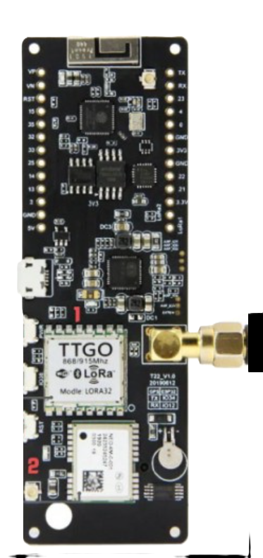
The LilyGo Tbeam is a compact and versatile development board designed for IoT (Internet of Things) and outdoor applications. Manufactured by LilyGo, this board integrates an ESP32 microcontroller, a GPS module, and multiple connectivity options, making it an excellent choice for projects requiring location tracking, wireless communication, and low-power operation. Its small form factor and robust feature set make it ideal for prototyping and deploying IoT solutions in real-world environments.
Explore Projects Built with LilyGo Tbeam


Explore Projects Built with LilyGo Tbeam
Common Applications and Use Cases
- GPS-based tracking systems (e.g., vehicle tracking, personal trackers)
- IoT devices with wireless communication (LoRa, Wi-Fi, Bluetooth)
- Environmental monitoring and data logging
- Outdoor navigation and geofencing applications
- Low-power, battery-operated IoT projects
Technical Specifications
The LilyGo Tbeam is packed with features that make it suitable for a wide range of applications. Below are its key technical specifications:
| Feature | Specification |
|---|---|
| Microcontroller | ESP32 (dual-core, 32-bit, 240 MHz, Wi-Fi, Bluetooth) |
| GPS Module | u-blox NEO-6M or NEO-M8N (depending on the version) |
| Connectivity | LoRa (SX1276/78), Wi-Fi, Bluetooth |
| Power Supply | 5V via USB-C or 3.7V LiPo battery |
| Battery Charging | Integrated LiPo battery charging circuit |
| GPIO Pins | 16 GPIO pins (configurable for digital/analog input/output) |
| Flash Memory | 4 MB |
| Operating Voltage | 3.3V (logic level) |
| Dimensions | 80 mm x 25 mm |
| Antenna | External LoRa and GPS antennas included |
| Power Consumption | Low-power modes supported (deep sleep, light sleep) |
Pin Configuration and Descriptions
The LilyGo Tbeam features a variety of pins for interfacing with external components. Below is the pinout description:
| Pin Name | Function | Description |
|---|---|---|
| 3V3 | Power Output | 3.3V power output for external components |
| GND | Ground | Common ground for the circuit |
| GPIO0 | General Purpose I/O | Configurable as digital/analog input/output |
| GPIO21 | I2C SDA | Data line for I2C communication |
| GPIO22 | I2C SCL | Clock line for I2C communication |
| TXD0 | UART TX | Transmit pin for UART communication |
| RXD0 | UART RX | Receive pin for UART communication |
| LoRa_DIO0 | LoRa Interrupt | Interrupt pin for LoRa communication |
| BAT | Battery Input | Connects to a 3.7V LiPo battery |
| GPS_TX | GPS Transmit | Transmit pin for GPS module |
| GPS_RX | GPS Receive | Receive pin for GPS module |
Usage Instructions
The LilyGo Tbeam is easy to use in a variety of projects. Below are the steps and best practices for using the board effectively:
How to Use the LilyGo Tbeam in a Circuit
Powering the Board:
- Connect a 5V power source via the USB-C port, or use a 3.7V LiPo battery connected to the BAT pin.
- Ensure the battery is properly connected to avoid reverse polarity damage.
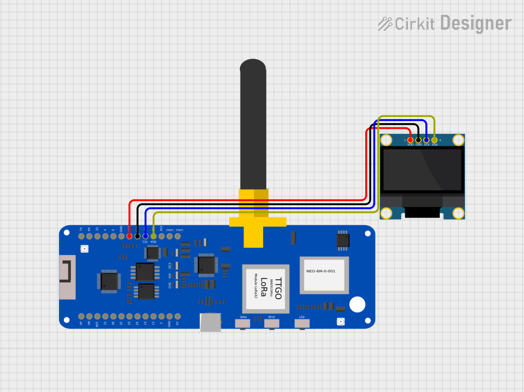
Connecting Peripherals:
- Use the GPIO pins to connect sensors, actuators, or other peripherals.
- For I2C devices, connect them to GPIO21 (SDA) and GPIO22 (SCL).
Programming the Board:
- Install the Arduino IDE and add the ESP32 board package.
- Select "LilyGo Tbeam" as the target board in the Arduino IDE.
- Connect the board to your computer via USB-C and upload your code.
Using GPS and LoRa:
- Attach the included GPS and LoRa antennas to their respective connectors.
- Use the appropriate libraries (e.g., TinyGPS++ for GPS, RadioHead for LoRa) to interface with these modules.
Important Considerations and Best Practices
- Antenna Placement: Ensure the GPS and LoRa antennas are securely connected and positioned for optimal signal reception.
- Power Management: Use the deep sleep mode of the ESP32 to reduce power consumption in battery-operated projects.
- Voltage Levels: The GPIO pins operate at 3.3V logic levels. Avoid connecting 5V signals directly to the pins to prevent damage.
- Firmware Updates: Regularly update the ESP32 firmware and libraries to ensure compatibility and access to the latest features.
Example Code for Arduino IDE
Below is an example code snippet to initialize the GPS module and read location data:
#include <TinyGPS++.h>
#include <HardwareSerial.h>

// Create a TinyGPS++ object
TinyGPSPlus gps;

// Initialize hardware serial for GPS communication
HardwareSerial gpsSerial(1);

void setup() {
  Serial.begin(115200); // Initialize serial monitor
  gpsSerial.begin(9600, SERIAL_8N1, 34, 12); // GPS TX=34, RX=12

  Serial.println("Initializing GPS...");
}

void loop() {
  // Read data from GPS module
  while (gpsSerial.available() > 0) {
    char c = gpsSerial.read();
    gps.encode(c); // Parse GPS data

    // If a valid location is available, print it
    if (gps.location.isUpdated()) {
      Serial.print("Latitude: ");
      Serial.println(gps.location.lat(), 6);
      Serial.print("Longitude: ");
      Serial.println(gps.location.lng(), 6);
    }
  }
}
Troubleshooting and FAQs
Common Issues and Solutions
GPS Not Acquiring Signal:
- Ensure the GPS antenna is connected and placed in an open area with a clear view of the sky.
- Wait for a few minutes for the GPS module to acquire a signal, especially during the first use.
LoRa Communication Fails:
- Verify that both transmitting and receiving devices are using the same frequency and settings.
- Check the LoRa antenna connection and ensure it is securely attached.
Board Not Detected by Computer:
- Ensure the USB-C cable is a data cable (not a charge-only cable).
- Install the correct USB drivers for the ESP32 if the board is not recognized.
High Power Consumption:
- Use the ESP32's deep sleep mode to reduce power usage in battery-powered applications.
- Disconnect unused peripherals to minimize current draw.
FAQs
Q: Can I use the LilyGo Tbeam without a battery?
A: Yes, the board can be powered directly via the USB-C port without a battery.
Q: What is the range of the LoRa module?
A: The range depends on the environment and antenna placement but can reach up to 10 km in open areas.
Q: How do I update the firmware?
A: Use the Arduino IDE or ESP32 flashing tools to upload new firmware to the board.
Q: Is the LilyGo Tbeam compatible with other GPS libraries?
A: Yes, it is compatible with libraries like TinyGPS++ and Adafruit GPS.
By following this documentation, you can effectively use the LilyGo Tbeam in your IoT and outdoor projects.