
How to Use AUDIO-JACK2: Examples, Pinouts, and Specs
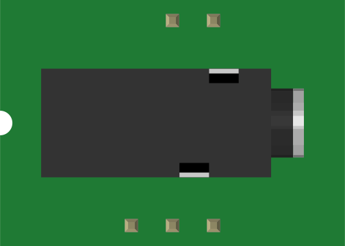
 Design with AUDIO-JACK2 in Cirkit Designer
Introduction
The AUDIO-JACK2 is a versatile audio connector designed for transmitting audio signals between devices. It is commonly used in headphones, speakers, audio amplifiers, and other audio equipment. This component provides a reliable and standardized interface for connecting audio devices, ensuring high-quality sound transmission. Its compact design and widespread compatibility make it a popular choice in consumer electronics.
Explore Projects Built with AUDIO-JACK2
 Open Project in Cirkit Designer
 Open Project in Cirkit Designer
 Open Project in Cirkit Designer
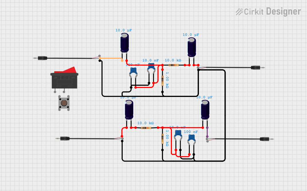 Open Project in Cirkit Designer
Explore Projects Built with AUDIO-JACK2
Open Project in Cirkit DesignerOpen Project in Cirkit DesignerOpen Project in Cirkit DesignerOpen Project in Cirkit DesignerCommon Applications
- Headphones and earphones
- Portable speakers
- Audio amplifiers and mixers
- Smartphones, tablets, and laptops
- Musical instruments and recording equipment
Technical Specifications
Key Technical Details
| Parameter | Value |
|---|---|
| Connector Type | 3.5mm TRS (Tip-Ring-Sleeve) |
| Number of Contacts | 3 (Stereo: Left, Right, Ground) |
| Maximum Voltage Rating | 12V DC |
| Maximum Current Rating | 1A |
| Material | Nickel-plated or gold-plated |
| Mounting Type | Through-hole or surface mount |
| Operating Temperature | -20°C to 70°C |
Pin Configuration and Descriptions
| Pin Name | Description | Typical Connection |
|---|---|---|
| Tip | Left audio channel | Left speaker or headphone |
| Ring | Right audio channel | Right speaker or headphone |
| Sleeve | Ground (common return path) | Ground of the circuit |
Usage Instructions
How to Use the AUDIO-JACK2 in a Circuit
- Identify the Pins: The AUDIO-JACK2 has three main contacts: Tip, Ring, and Sleeve. Ensure you correctly identify these pins before connecting.
- Soldering: If using a through-hole version, insert the pins into the PCB and solder them securely. For surface-mount versions, align the connector pads with the PCB pads and solder carefully.
- Connect Audio Signals:
- Connect the Tip to the left audio channel output of your circuit.
- Connect the Ring to the right audio channel output.
- Connect the Sleeve to the ground of your circuit.
- Test the Connection: After wiring, test the audio output using headphones or speakers to ensure proper functionality.
Important Considerations and Best Practices
- Avoid Overloading: Do not exceed the maximum voltage (12V DC) or current (1A) ratings to prevent damage.
- Use Shielded Cables: For optimal audio quality, use shielded cables to minimize noise and interference.
- Secure Mounting: Ensure the AUDIO-JACK2 is securely mounted to prevent mechanical stress on the solder joints.
- Polarity: Double-check the polarity of the connections to avoid reversed audio channels.
Example: Connecting AUDIO-JACK2 to an Arduino UNO
The AUDIO-JACK2 can be used to output audio signals generated by an Arduino UNO. Below is an example of generating a simple tone:
/*
  Example: Generating a tone using Arduino and AUDIO-JACK2
  This code generates a 1kHz tone on pin 9, which can be connected to the Tip
  of the AUDIO-JACK2. The Ring and Sleeve can be connected to ground.
*/

const int audioPin = 9; // Pin connected to the Tip of AUDIO-JACK2

void setup() {
  pinMode(audioPin, OUTPUT); // Set the audio pin as an output
}

void loop() {
  // Generate a 1kHz square wave
  tone(audioPin, 1000); // Play a 1kHz tone
  delay(1000);          // Play for 1 second
  noTone(audioPin);     // Stop the tone
  delay(1000);          // Wait for 1 second
}
Connections:
- Connect
audioPin(Pin 9) to the Tip of the AUDIO-JACK2. - Connect the Sleeve to the Arduino GND.
- The Ring can also be connected to GND for mono output.
Troubleshooting and FAQs
Common Issues
No Sound Output:
- Cause: Incorrect wiring or loose connections.
- Solution: Verify the connections to the Tip, Ring, and Sleeve. Ensure the solder joints are secure.
Distorted Audio:
- Cause: Exceeding voltage or current ratings, or interference.
- Solution: Use shielded cables and ensure the input signal is within the specified range.
Reversed Audio Channels:
- Cause: Tip and Ring connections swapped.
- Solution: Double-check the wiring and ensure the Tip is connected to the left channel and the Ring to the right channel.
Mechanical Damage:
- Cause: Excessive force applied to the connector.
- Solution: Use strain relief mechanisms to protect the connector from mechanical stress.
FAQs
Q1: Can the AUDIO-JACK2 be used for mono audio?
A1: Yes, for mono audio, connect the Tip and Ring together to the audio signal, and the Sleeve to ground.
Q2: Is the AUDIO-JACK2 compatible with 6.35mm (1/4 inch) jacks?
A2: No, the AUDIO-JACK2 is a 3.5mm connector. However, adapters are available to convert between 3.5mm and 6.35mm jacks.
Q3: Can I use the AUDIO-JACK2 for microphone input?
A3: The AUDIO-JACK2 is typically used for audio output. For microphone input, a TRRS (Tip-Ring-Ring-Sleeve) connector may be required.
Q4: What materials are recommended for better durability?
A4: Gold-plated connectors are recommended for improved durability and corrosion resistance.