How to Use MCP4725: Examples, Pinouts, and Specs
Introduction
The MCP4725 is a 12-bit digital-to-analog converter (DAC) with an I2C interface, designed for seamless integration into microcontroller-based projects. This component allows for precise digital-to-analog signal conversion, making it ideal for applications requiring analog output, such as audio signal generation, waveform synthesis, and sensor calibration.
One of the standout features of the MCP4725 is its onboard EEPROM, which can store the last output value, ensuring that the DAC retains its state even after a power cycle. The device operates over a voltage range of 0V to VDD, providing flexibility for various applications.
Explore Projects Built with MCP4725


Explore Projects Built with MCP4725
Common Applications
- Audio signal generation
- Waveform generation and synthesis
- Sensor calibration and testing
- Analog control systems
- Voltage reference generation
Technical Specifications
Key Technical Details
- Resolution: 12-bit (4096 steps)
- Interface: I2C (up to 3.4 MHz)
- Output Voltage Range: 0V to VDD
- Supply Voltage (VDD): 2.7V to 5.5V
- EEPROM: Stores the last DAC output value
- Output Current: Up to 25 mA
- Power Consumption: Low-power operation
- Package Types: SOT-23-6, MSOP-8
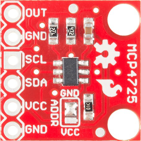
Pin Configuration and Descriptions
The MCP4725 is typically available in a 6-pin SOT-23 package. Below is the pinout description:
| Pin | Name | Description |
|---|---|---|
| 1 | VDD | Power supply input (2.7V to 5.5V). |
| 2 | SDA | I2C data line. Used for communication with the microcontroller. |
| 3 | VSS | Ground connection. |
| 4 | OUT | Analog output voltage (0V to VDD). |
| 5 | SCL | I2C clock line. Used for synchronizing data transfer. |
| 6 | A0 | I2C address selection pin. Allows for multiple MCP4725 devices on the same bus. |
Usage Instructions
How to Use the MCP4725 in a Circuit
- Power Supply: Connect the VDD pin to a power source (2.7V to 5.5V) and the VSS pin to ground.
- I2C Communication: Connect the SDA and SCL pins to the corresponding I2C pins on your microcontroller. Use pull-up resistors (typically 4.7kΩ) on both lines.
- Analog Output: The OUT pin provides the analog voltage output. Connect this pin to the desired load or circuit.
- Address Selection: Use the A0 pin to set the I2C address. This allows multiple MCP4725 devices to share the same I2C bus.
Important Considerations
- Ensure the I2C pull-up resistors are properly connected to avoid communication issues.
- Avoid exceeding the maximum output current (25 mA) to prevent damage to the device.
- Use decoupling capacitors (e.g., 0.1 µF) near the VDD pin to reduce noise and improve stability.
- If using the EEPROM feature, note that excessive write cycles can wear out the memory (typical endurance is 1,000,000 cycles).
Example Code for Arduino UNO
Below is an example of how to use the MCP4725 with an Arduino UNO to output a sine wave:
#include <Wire.h>
#include <Adafruit_MCP4725.h>

// Create an MCP4725 object
Adafruit_MCP4725 dac;

void setup() {
  // Initialize serial communication for debugging
  Serial.begin(9600);

  // Initialize the MCP4725 DAC
  if (!dac.begin(0x60)) { // 0x60 is the default I2C address
    Serial.println("Failed to find MCP4725. Check connections.");
    while (1);
  }
  Serial.println("MCP4725 initialized.");
}

void loop() {
  // Generate a sine wave using the DAC
  for (int i = 0; i < 4096; i++) {
    // Calculate the sine wave value (scaled to 12-bit range)
    uint16_t value = (sin(i * 2 * PI / 4096) + 1) * 2047;

    // Write the value to the DAC
    dac.setVoltage(value, false); // 'false' means do not write to EEPROM

    // Small delay to control the frequency of the sine wave
    delayMicroseconds(100);
  }
}
Notes on the Code
- The
Adafruit_MCP4725library is used for easy communication with the DAC. Install it via the Arduino Library Manager. - The sine wave is generated by scaling the
sin()function to the 12-bit range (0 to 4095). - The
setVoltage()function writes the calculated value to the DAC. The second parameter determines whether to store the value in EEPROM.
Troubleshooting and FAQs
Common Issues
No Output Voltage:
- Check the power supply connections (VDD and VSS).
- Verify the I2C connections (SDA and SCL) and ensure pull-up resistors are present.
- Confirm the I2C address matches the one used in the code.
Incorrect Output Voltage:
- Ensure the input values to the DAC are within the 12-bit range (0 to 4095).
- Verify that the load connected to the OUT pin does not exceed the maximum current rating.
I2C Communication Failure:
- Check the wiring and ensure the SDA and SCL lines are not swapped.
- Verify the pull-up resistors are correctly connected.
- Ensure the microcontroller and MCP4725 share a common ground.
FAQs
Can I use multiple MCP4725 devices on the same I2C bus? Yes, you can use multiple devices by configuring their A0 pins to set unique I2C addresses.
What happens if I write to the EEPROM too often? The EEPROM has a limited write endurance of 1,000,000 cycles. Avoid frequent writes to prolong its lifespan.
Can the MCP4725 output negative voltages? No, the output voltage range is limited to 0V to VDD.
What is the maximum output current of the MCP4725? The maximum output current is 25 mA. Exceeding this limit may damage the device.
By following this documentation, you can effectively integrate the MCP4725 into your projects and achieve precise digital-to-analog signal conversion.