How to Use CEE 16A 3P 6H 200-250VAC IP44: Examples, Pinouts, and Specs
Introduction
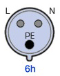
The CEE 16A 3P 6H 200-250VAC IP44 is a robust industrial-grade connector designed for reliable power distribution in demanding environments. This connector is part of the IEC 60309 standard (commonly referred to as "Commando" connectors) and is rated for 16A current, 3-phase power, and 200-250VAC applications. Its IP44 rating ensures protection against solid objects larger than 1mm and water splashes, making it suitable for outdoor and industrial use.
Explore Projects Built with CEE 16A 3P 6H 200-250VAC IP44


Explore Projects Built with CEE 16A 3P 6H 200-250VAC IP44
Common Applications and Use Cases
- Industrial machinery and equipment
- Temporary power distribution at construction sites
- Outdoor events and stage lighting
- Marine and dockside power connections
- Portable generators and heavy-duty appliances
Technical Specifications
Key Technical Details
| Parameter | Specification |
|---|---|
| Rated Current | 16A |
| Rated Voltage | 200-250VAC |
| Number of Phases | 3 |
| Frequency | 50/60 Hz |
| Number of Pins | 6 (including earth and neutral) |
| Protection Rating | IP44 |
| Operating Temperature | -25°C to +40°C |
| Housing Material | High-impact thermoplastic |
| Standard Compliance | IEC 60309 |
Pin Configuration and Descriptions
| Pin Number | Pin Name | Description |
|---|---|---|
| 1 | L1 (Phase 1) | First phase of the 3-phase power supply |
| 2 | L2 (Phase 2) | Second phase of the 3-phase power supply |
| 3 | L3 (Phase 3) | Third phase of the 3-phase power supply |
| 4 | N (Neutral) | Neutral connection |
| 5 | PE (Earth) | Protective earth/ground connection |
| 6 | Auxiliary Pin | Optional auxiliary connection |
Usage Instructions
How to Use the Component in a Circuit
Wiring the Connector:
- Ensure the power supply is turned off before wiring.
- Strip the insulation from the wires to expose the conductors.
- Connect the wires to the appropriate terminals inside the connector:
- L1, L2, and L3 for the three-phase lines.
- N for the neutral wire.
- PE for the protective earth wire.
- Tighten the terminal screws securely to ensure a reliable connection.
- Reassemble the connector housing and ensure it is properly sealed.
Connecting to a Power Source:
- Align the connector's pins with the corresponding socket.
- Insert the connector fully and twist to lock it in place (if applicable).
Powering On:
- Once the connector is securely connected, turn on the power supply.
- Verify that the connected equipment is functioning correctly.
Important Considerations and Best Practices
- IP44 Rating: While the connector is splash-proof, avoid submerging it in water.
- Cable Selection: Use cables rated for at least 16A and suitable for the operating voltage.
- Inspection: Regularly inspect the connector for signs of wear, damage, or corrosion.
- Proper Grounding: Ensure the PE (earth) connection is securely wired to prevent electrical hazards.
- Compatibility: Use only with sockets and plugs that comply with the IEC 60309 standard.
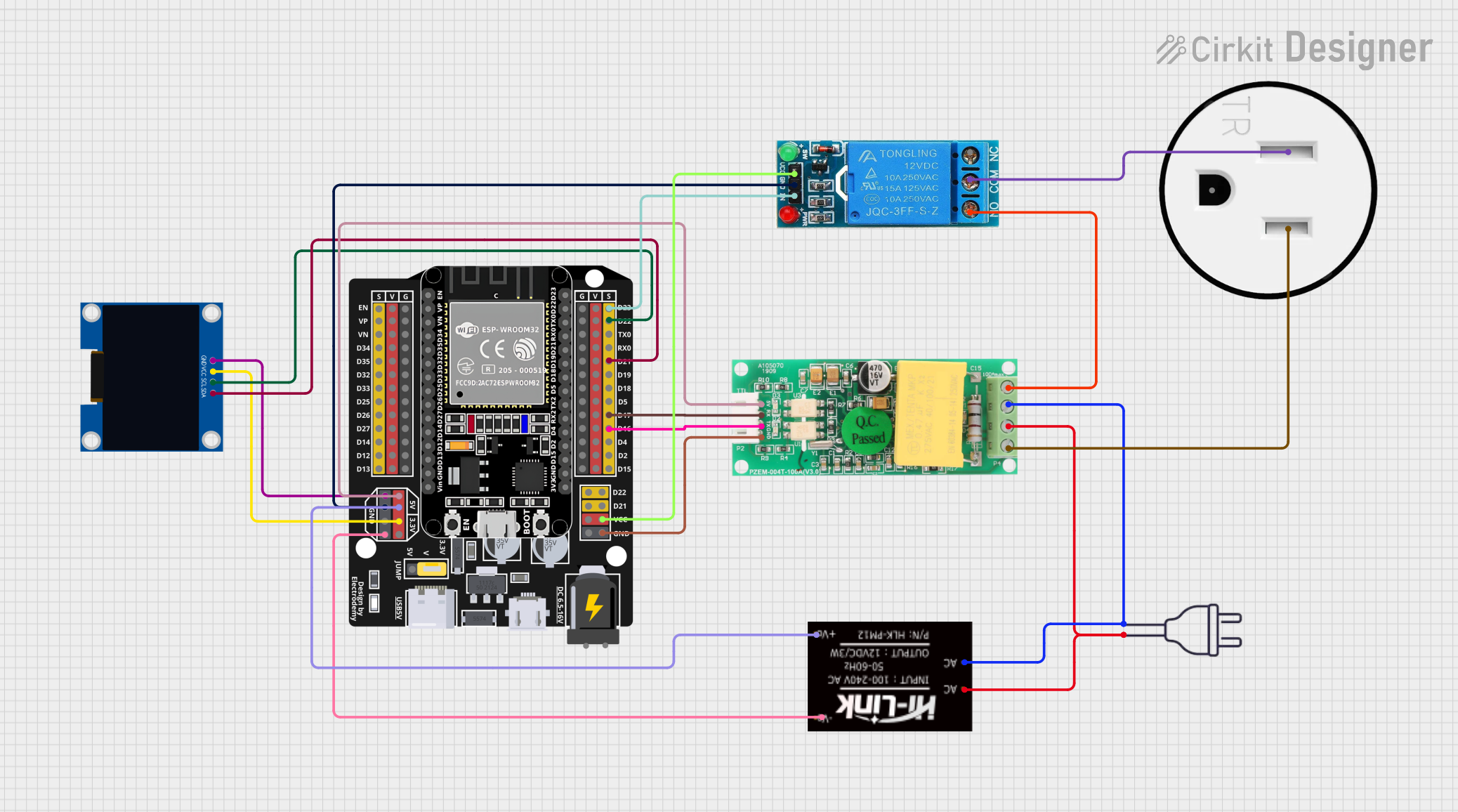
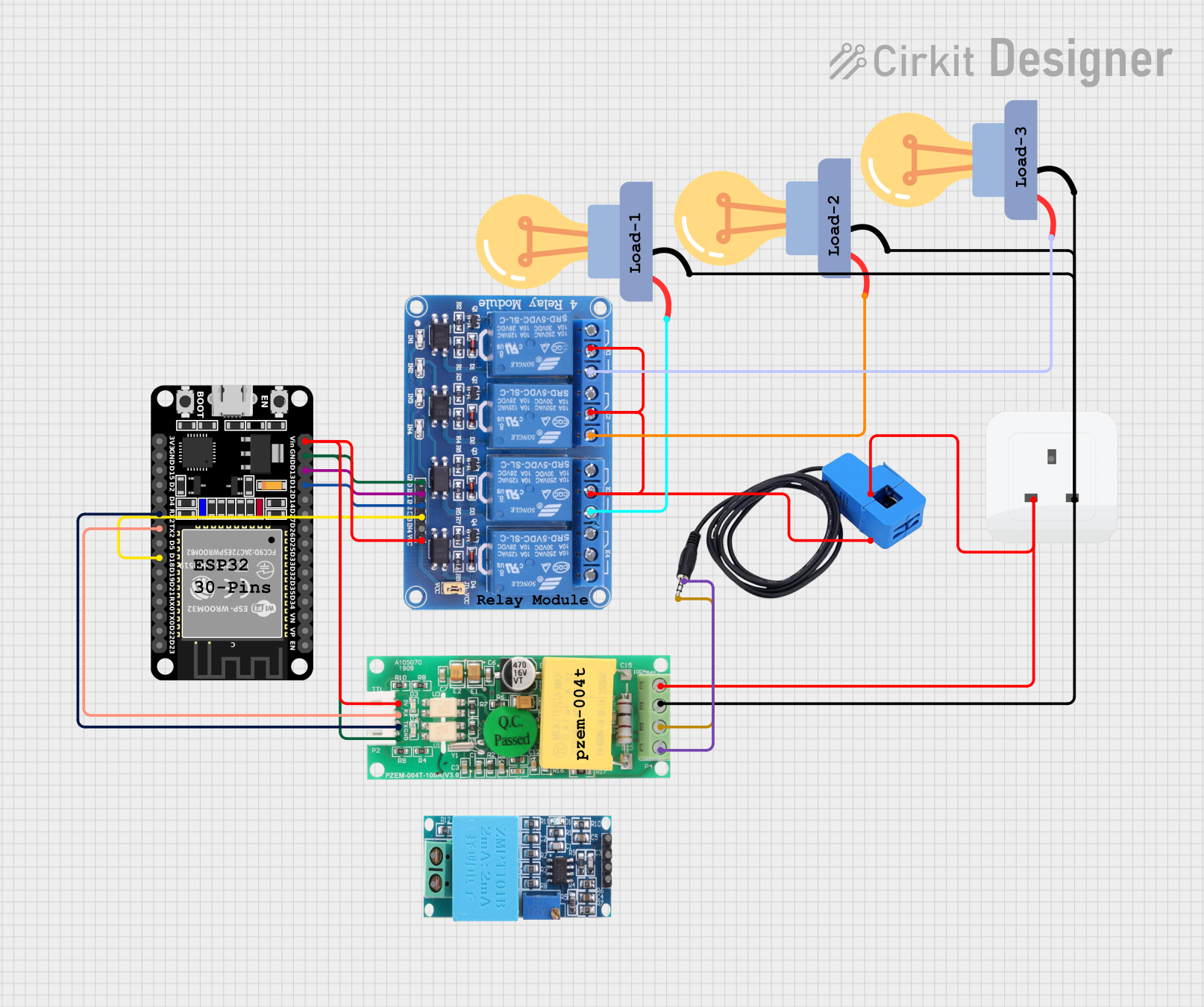
Example: Connecting to an Arduino UNO (via a Relay Module)
While the CEE 16A connector is not directly compatible with low-power devices like an Arduino UNO, it can be used to control high-power equipment via a relay module. Below is an example of how to use an Arduino UNO to control a device powered by the CEE connector.
/*
  Example: Controlling a device powered by a CEE 16A connector
  using an Arduino UNO and a relay module.

  Note: Ensure the relay module is rated for the voltage and current
  of the connected device. This example assumes a 5V relay module.
*/

const int relayPin = 7; // Pin connected to the relay module

void setup() {
  pinMode(relayPin, OUTPUT); // Set the relay pin as an output
  digitalWrite(relayPin, LOW); // Ensure the relay is off initially
}

void loop() {
  // Turn the relay on (activates the connected device)
  digitalWrite(relayPin, HIGH);
  delay(5000); // Keep the device on for 5 seconds

  // Turn the relay off (deactivates the connected device)
  digitalWrite(relayPin, LOW);
  delay(5000); // Keep the device off for 5 seconds
}
Warning: Always exercise caution when working with high-voltage equipment. Ensure proper isolation between the Arduino and the high-voltage circuit using an optocoupler-based relay module.
Troubleshooting and FAQs
Common Issues Users Might Face
Loose Connections:
- Symptom: The connected device intermittently loses power.
- Solution: Check that all wires are securely fastened to the connector terminals.
Overheating:
- Symptom: The connector becomes excessively hot during operation.
- Solution: Ensure the current does not exceed 16A and that the connector is properly ventilated.
Water Ingress:
- Symptom: The connector malfunctions after exposure to water.
- Solution: Dry the connector thoroughly and inspect for damage. Replace if necessary.
Corrosion:
- Symptom: The pins or terminals show signs of rust or corrosion.
- Solution: Clean the affected areas with a contact cleaner and apply a protective coating.
Solutions and Tips for Troubleshooting
- Verify Voltage and Current Ratings: Ensure the connected equipment does not exceed the connector's rated specifications.
- Inspect the IP44 Seal: Check that the housing is properly assembled to maintain the IP44 protection.
- Test Continuity: Use a multimeter to verify continuity between the pins and the connected wires.
- Replace Damaged Components: If the connector shows signs of physical damage, replace it immediately to avoid safety hazards.
By following this documentation, users can safely and effectively utilize the CEE 16A 3P 6H 200-250VAC IP44 connector in their applications.