
How to Use A6282: Examples, Pinouts, and Specs
 Design with A6282 in Cirkit Designer
Introduction
The A6282, manufactured by Allegro MicroSystems (Part ID: A6282ELP-T), is a dual H-bridge motor driver IC designed for controlling DC motors and stepper motors. This versatile component is ideal for applications requiring precise motor control, such as robotics, automation systems, and industrial equipment. With built-in protection features like overcurrent protection and thermal shutdown, the A6282 ensures reliable operation even in demanding environments.
Explore Projects Built with A6282
 Open Project in Cirkit Designer
 Open Project in Cirkit Designer
 Open Project in Cirkit Designer
 Open Project in Cirkit Designer
Explore Projects Built with A6282
Open Project in Cirkit DesignerOpen Project in Cirkit DesignerOpen Project in Cirkit DesignerOpen Project in Cirkit DesignerCommon Applications
- Robotics (e.g., robotic arms, mobile robots)
- Automation systems
- Stepper motor control in CNC machines
- DC motor control in consumer electronics
- Industrial equipment requiring motorized actuation
Technical Specifications
Key Technical Details
| Parameter | Value |
|---|---|
| Supply Voltage (Vcc) | 8 V to 50 V |
| Output Current (per H-bridge) | Up to 1 A continuous, 2 A peak |
| Logic Input Voltage Range | 0 V to 5 V (TTL/CMOS compatible) |
| Control Interface | PWM (Pulse Width Modulation) |
| Operating Temperature Range | -20°C to +85°C |
| Protection Features | Overcurrent protection, thermal shutdown |
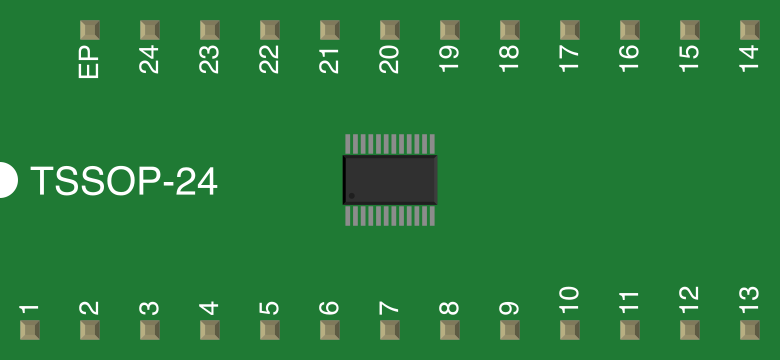
| Package Type | 16-pin TSSOP |
Pin Configuration and Descriptions
The A6282 is housed in a 16-pin TSSOP package. Below is the pinout and description:
| Pin Number | Pin Name | Description |
|---|---|---|
| 1 | OUT1A | Output for H-bridge 1 (A-side) |
| 2 | OUT1B | Output for H-bridge 1 (B-side) |
| 3 | GND | Ground |
| 4 | VBB | Motor supply voltage (8 V to 50 V) |
| 5 | OUT2A | Output for H-bridge 2 (A-side) |
| 6 | OUT2B | Output for H-bridge 2 (B-side) |
| 7 | ENABLE1 | Enable input for H-bridge 1 |
| 8 | ENABLE2 | Enable input for H-bridge 2 |
| 9 | PWM1 | PWM input for H-bridge 1 |
| 10 | PWM2 | PWM input for H-bridge 2 |
| 11 | FAULT | Fault output (active low) |
| 12 | VDD | Logic supply voltage (3.3 V or 5 V) |
| 13 | IN1 | Logic input for H-bridge 1 |
| 14 | IN2 | Logic input for H-bridge 2 |
| 15 | NC | No connection |
| 16 | NC | No connection |
Usage Instructions
How to Use the A6282 in a Circuit
- Power Supply: Connect the motor supply voltage (8 V to 50 V) to the
VBBpin and the logic supply voltage (3.3 V or 5 V) to theVDDpin. Ensure proper decoupling capacitors are placed near the pins to reduce noise. - Motor Connections: Connect the motor terminals to the
OUT1A,OUT1B,OUT2A, andOUT2Bpins, depending on whether you are driving one or two motors. - Control Signals: Use the
ENABLE1andENABLE2pins to enable or disable the H-bridges. Provide PWM signals to thePWM1andPWM2pins to control motor speed. Use theIN1andIN2pins to set the direction of rotation. - Fault Monitoring: Monitor the
FAULTpin for any error conditions. This pin is active low and will indicate issues like overcurrent or thermal shutdown.
Important Considerations
- Heat Dissipation: The A6282 can generate heat during operation. Use a proper heat sink or ensure adequate ventilation to prevent overheating.
- Protection Features: The IC includes built-in overcurrent and thermal shutdown protection. However, ensure the motor's current rating does not exceed the IC's maximum ratings.
- Decoupling Capacitors: Place a 0.1 µF ceramic capacitor close to the
VDDpin and a larger electrolytic capacitor (e.g., 100 µF) near theVBBpin to stabilize the power supply.
Example: Using A6282 with Arduino UNO
Below is an example of how to control a DC motor using the A6282 and an Arduino UNO:
// Define pin connections
const int enablePin = 9;  // Connect to ENABLE1 pin of A6282
const int pwmPin = 10;    // Connect to PWM1 pin of A6282
const int in1Pin = 7;     // Connect to IN1 pin of A6282
const int in2Pin = 8;     // Connect to IN2 pin of A6282

void setup() {
  // Set pin modes
  pinMode(enablePin, OUTPUT);
  pinMode(pwmPin, OUTPUT);
  pinMode(in1Pin, OUTPUT);
  pinMode(in2Pin, OUTPUT);

  // Enable the H-bridge
  digitalWrite(enablePin, HIGH);
}

void loop() {
  // Rotate motor in one direction
  digitalWrite(in1Pin, HIGH);  // Set IN1 high
  digitalWrite(in2Pin, LOW);   // Set IN2 low
  analogWrite(pwmPin, 128);    // Set motor speed (0-255)

  delay(2000); // Run for 2 seconds

  // Rotate motor in the opposite direction
  digitalWrite(in1Pin, LOW);   // Set IN1 low
  digitalWrite(in2Pin, HIGH);  // Set IN2 high
  analogWrite(pwmPin, 128);    // Set motor speed (0-255)

  delay(2000); // Run for 2 seconds
}
Troubleshooting and FAQs
Common Issues and Solutions
Motor Not Spinning
- Cause: Incorrect wiring or insufficient power supply.
- Solution: Double-check all connections, ensure the motor supply voltage is within the specified range, and verify that the
ENABLEandPWMpins are correctly configured.
Overheating
- Cause: Excessive current draw or inadequate heat dissipation.
- Solution: Ensure the motor's current rating does not exceed the IC's maximum continuous current. Use a heat sink or improve ventilation.
FAULT Pin Active (Low)
- Cause: Overcurrent or thermal shutdown triggered.
- Solution: Check for short circuits in the motor connections and reduce the load on the motor. Allow the IC to cool down if thermal shutdown occurred.
PWM Control Not Working
- Cause: Incorrect PWM signal or incompatible logic voltage.
- Solution: Verify that the PWM signal is within the logic voltage range (0 V to 5 V). Ensure the Arduino or microcontroller is properly configured to generate PWM signals.
FAQs
Can the A6282 drive stepper motors? Yes, the A6282 can drive stepper motors by controlling the two H-bridges independently. Use appropriate stepper motor control algorithms.
What happens if the motor draws more than 1 A continuously? The IC's overcurrent protection will activate, and the
FAULTpin will go low. Prolonged overcurrent conditions may trigger thermal shutdown.Is the A6282 compatible with 3.3 V logic? Yes, the A6282 supports both 3.3 V and 5 V logic levels for control inputs.
This concludes the documentation for the A6282 dual H-bridge motor driver IC.