How to Use THAT_1206_Breakout: Examples, Pinouts, and Specs
Introduction
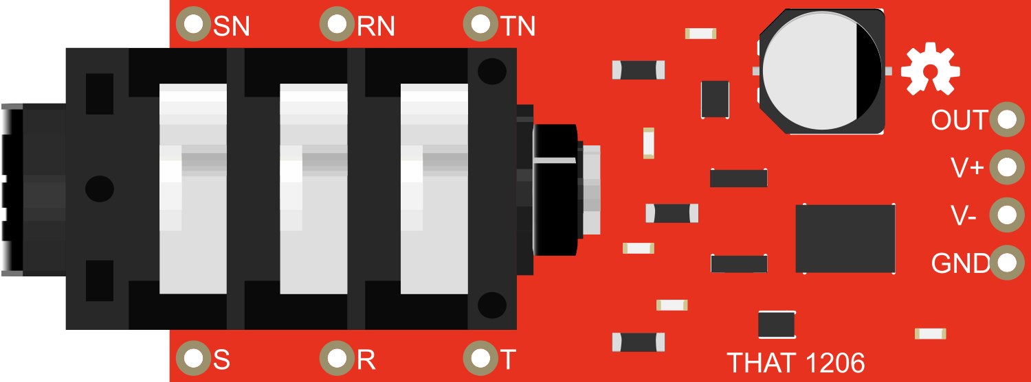
The THAT_1206_Breakout is a specialized breakout board designed to facilitate the use of the THAT 1206 integrated circuit. The THAT 1206 IC is a high-performance, low-noise balanced line receiver commonly used in professional audio equipment. It is designed to receive and amplify balanced audio signals with minimal distortion and noise, making it ideal for applications in audio recording, mixing consoles, and playback systems.
Explore Projects Built with THAT_1206_Breakout


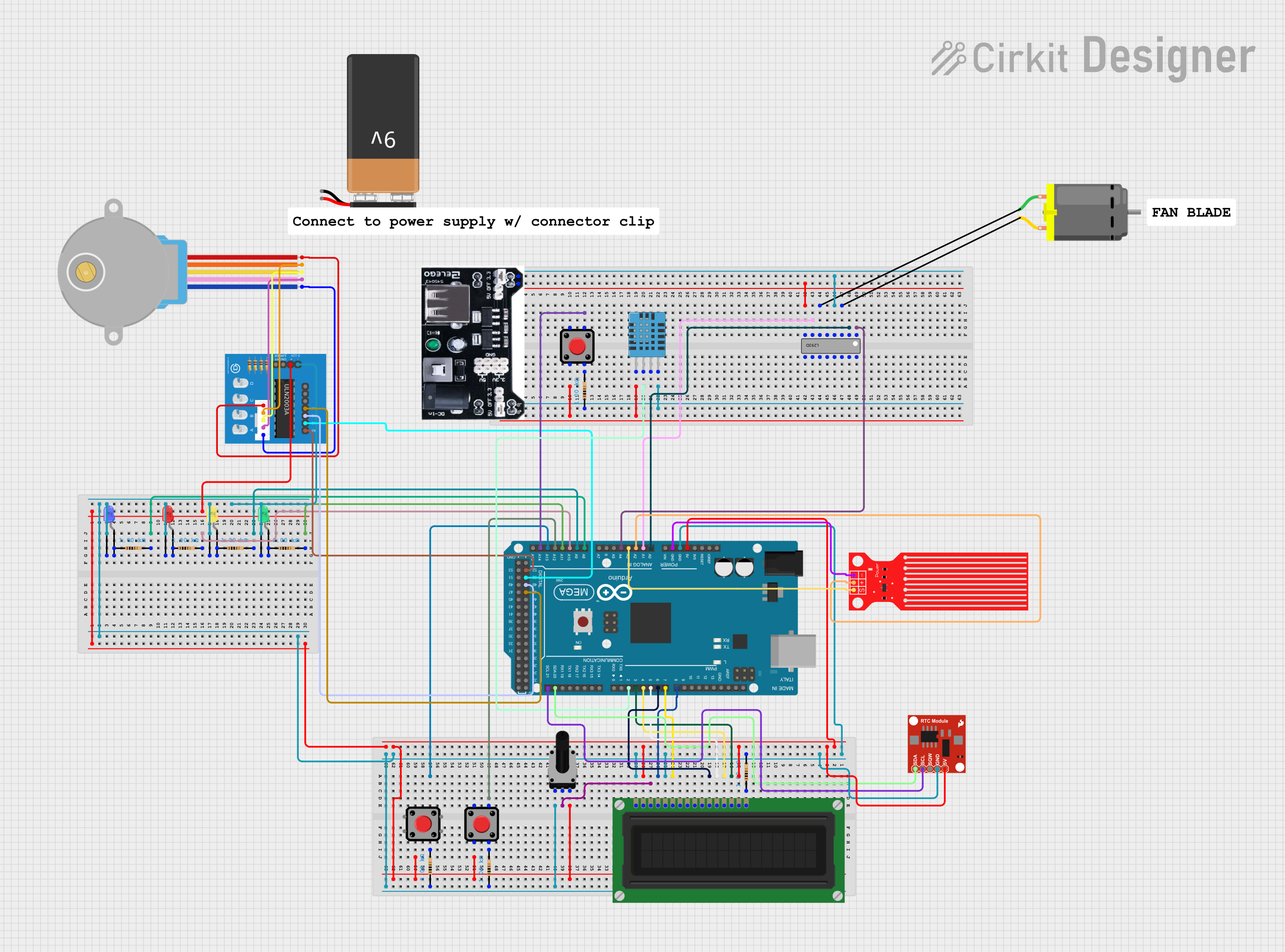

Explore Projects Built with THAT_1206_Breakout
Common Applications and Use Cases
- Professional audio recording studios
- Live sound reinforcement systems
- Broadcast audio
- High-fidelity audio playback systems
- Audio interface input stages
Technical Specifications
Key Technical Details
- Supply Voltage (V+ to V-): ±4V to ±18V
- Input Common-Mode Rejection Ratio (CMRR): 90dB typ. at 60Hz
- Total Harmonic Distortion (THD+N): 0.0006% typ.
- Equivalent Input Noise (EIN): -129.5dBu
- Bandwidth: >200kHz
Pin Configuration and Descriptions
| Pin Number | Name | Description |
|---|---|---|
| 1 | IN+ | Non-inverting audio signal input |
| 2 | IN- | Inverting audio signal input |
| 3 | V- | Negative power supply input |
| 4 | GND | Ground connection |
| 5 | V+ | Positive power supply input |
| 6 | OUT+ | Non-inverting audio signal output |
| 7 | OUT- | Inverting audio signal output |
Usage Instructions
How to Use the Component in a Circuit
Power Supply: Connect a bipolar power supply to the V+ and V- pins, ensuring that the voltage is within the specified range (±4V to ±18V).
Input Connections: Connect the balanced audio source to the IN+ and IN- pins. For unbalanced sources, connect the signal to IN+ and ground the IN- pin.
Output Connections: Connect the OUT+ and OUT- pins to the next stage in your audio processing chain. For unbalanced output, use OUT+ and ground OUT-.
Grounding: Connect the GND pin to the system ground. Ensure that the ground layout minimizes noise and interference.
Important Considerations and Best Practices
- Use short, shielded cables for audio connections to minimize noise pickup.
- Keep the power supply lines as clean as possible to prevent power supply noise from affecting the audio signal.
- Implement proper PCB layout techniques to avoid ground loops and crosstalk.
- Ensure that the breakout board is mounted securely to prevent microphonics (noise due to mechanical vibrations).
Troubleshooting and FAQs
Common Issues Users Might Face
- Noise in the Audio Signal: Ensure that the breakout board is properly grounded and that cables are shielded. Check the power supply for stability and cleanliness.
- Distorted Audio Output: Verify that the input signal levels are within the acceptable range and that the power supply voltages are correct.
- No Audio Output: Check the connections to the IN+, IN-, OUT+, and OUT- pins. Ensure that the power supply is connected and within the specified voltage range.
Solutions and Tips for Troubleshooting
- If you encounter noise, try re-routing audio and power cables, and check for proper grounding.
- For distorted audio, reduce the input signal level or check for overvoltage at the power supply.
- In case of no audio output, double-check all connections and measure the supply voltage to ensure it is within the specified range.
FAQs
Q: Can I use the THAT_1206_Breakout with an unbalanced audio source? A: Yes, you can. Connect the signal to IN+ and ground the IN- pin.
Q: What should I do if I'm getting a hum in the audio signal? A: A hum is often caused by ground loops. Ensure that all audio equipment shares a common ground point and that cables are properly shielded.
Q: Is it possible to run the THAT_1206_Breakout on a single-ended power supply? A: No, the THAT 1206 IC requires a bipolar power supply to operate correctly.
Q: How can I connect the THAT_1206_Breakout to an Arduino UNO? A: The THAT_1206_Breakout is an audio component and does not directly interface with digital pins of an Arduino UNO. However, you can use an Arduino to control other aspects of the audio circuit, such as volume or tone, with additional components like digital potentiometers or signal processors.
Note: This documentation is for informational purposes only. Always consult the original manufacturer's datasheet for the most accurate and detailed information.