How to Use Motor Controller With Current Protection: Examples, Pinouts, and Specs
Introduction
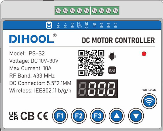
The DIHOOL IPS-S2 Motor Controller With Current Protection is a versatile and reliable device designed to regulate the speed and direction of DC motors. It features built-in overcurrent protection to safeguard motors and connected circuits from damage caused by excessive current. This component is ideal for applications requiring precise motor control, such as robotics, automation systems, and electric vehicles.
Explore Projects Built with Motor Controller With Current Protection
Explore Projects Built with Motor Controller With Current Protection
Common Applications
- Robotics and mechatronics projects
- Conveyor belt systems
- Electric vehicles and scooters
- Industrial automation
- DIY motorized projects
Technical Specifications
The following table outlines the key technical details of the DIHOOL IPS-S2 motor controller:
| Parameter | Value |
|---|---|
| Operating Voltage Range | 6V to 30V |
| Maximum Continuous Current | 10A |
| Peak Current (Protection Trigger) | 15A |
| PWM Frequency Range | 1 kHz to 20 kHz |
| Control Signal Voltage | 3.3V or 5V logic compatible |
| Motor Channels | 1 (Single Motor) |
| Direction Control | Forward/Reverse |
| Overcurrent Protection | Automatic shutdown at >15A |
| Dimensions | 50mm x 30mm x 15mm |
| Operating Temperature | -20°C to 85°C |
Pin Configuration and Descriptions
The DIHOOL IPS-S2 has a simple pinout for easy integration into circuits. The pin configuration is as follows:
| Pin Name | Type | Description |
|---|---|---|
| VIN | Power Input | Connect to the positive terminal of the power supply (6V-30V). |
| GND | Power Ground | Connect to the ground terminal of the power supply. |
| OUT+ | Motor Output | Connect to the positive terminal of the motor. |
| OUT- | Motor Output | Connect to the negative terminal of the motor. |
| PWM | Control Input | Pulse Width Modulation input for speed control. Accepts 3.3V or 5V logic. |
| DIR | Control Input | Direction control input. HIGH for forward, LOW for reverse. |
| EN | Control Input | Enable pin. HIGH to enable the motor, LOW to disable it. |
Usage Instructions
How to Use the Component in a Circuit
- Power Supply Connection: Connect the VIN pin to a DC power supply (6V-30V) and the GND pin to the ground of the power supply.
- Motor Connection: Connect the motor terminals to the OUT+ and OUT- pins.
- Control Signals:
- Use the PWM pin to control the motor speed. A higher duty cycle increases the speed.
- Use the DIR pin to set the motor direction. Set HIGH for forward and LOW for reverse.
- Use the EN pin to enable or disable the motor. Set HIGH to enable and LOW to disable.
- Overcurrent Protection: The controller will automatically shut down if the current exceeds 15A. Reduce the load or check for short circuits before restarting.
Important Considerations and Best Practices
- Ensure the power supply voltage matches the motor's operating voltage range.
- Use a heatsink or active cooling if operating near the maximum current limit for extended periods.
- Avoid sudden changes in direction at high speeds to prevent mechanical stress on the motor.
- Use appropriate decoupling capacitors near the VIN pin to reduce noise and voltage spikes.
- For Arduino or microcontroller integration, ensure the control signals (PWM, DIR, EN) are within the 3.3V or 5V logic levels.
Example Arduino Code
Below is an example of how to control the DIHOOL IPS-S2 with an Arduino UNO:
// Define pin connections
const int pwmPin = 9;  // PWM signal for speed control
const int dirPin = 8;  // Direction control
const int enPin = 7;   // Enable pin

void setup() {
  // Set pin modes
  pinMode(pwmPin, OUTPUT);
  pinMode(dirPin, OUTPUT);
  pinMode(enPin, OUTPUT);

  // Initialize motor state
  digitalWrite(enPin, HIGH);  // Enable the motor
  digitalWrite(dirPin, HIGH); // Set direction to forward
}

void loop() {
  // Gradually increase motor speed
  for (int speed = 0; speed <= 255; speed++) {
    analogWrite(pwmPin, speed); // Set PWM duty cycle (0-255)
    delay(20);                  // Wait for 20ms
  }

  // Change direction after reaching full speed
  digitalWrite(dirPin, LOW);    // Reverse direction
  delay(2000);                  // Run in reverse for 2 seconds

  // Gradually decrease motor speed
  for (int speed = 255; speed >= 0; speed--) {
    analogWrite(pwmPin, speed); // Decrease PWM duty cycle
    delay(20);                  // Wait for 20ms
  }

  // Stop the motor
  digitalWrite(enPin, LOW);     // Disable the motor
  delay(2000);                  // Wait for 2 seconds before restarting
}
Troubleshooting and FAQs
Common Issues and Solutions
Motor Does Not Spin:
- Ensure the EN pin is set HIGH to enable the motor.
- Verify the power supply voltage is within the 6V-30V range.
- Check the motor connections to OUT+ and OUT-.
Motor Spins in the Wrong Direction:
- Reverse the logic level on the DIR pin (HIGH for forward, LOW for reverse).
- Verify the motor wiring to ensure proper polarity.
Overcurrent Shutdown:
- Check for mechanical obstructions or excessive load on the motor.
- Ensure the motor's rated current does not exceed the controller's 10A continuous limit.
PWM Signal Not Working:
- Verify the PWM signal is within the 1 kHz to 20 kHz frequency range.
- Ensure the PWM pin is connected to a 3.3V or 5V logic source.
FAQs
Q: Can I use this controller with a 24V motor?
A: Yes, the DIHOOL IPS-S2 supports motors with operating voltages between 6V and 30V, including 24V motors.
Q: What happens if the current exceeds 15A?
A: The controller will automatically shut down to protect the motor and circuit. Reduce the load or check for short circuits before restarting.
Q: Is the controller compatible with 3.3V microcontrollers like the ESP32?
A: Yes, the control pins (PWM, DIR, EN) are compatible with both 3.3V and 5V logic levels.
Q: Can I control multiple motors with this controller?
A: No, the DIHOOL IPS-S2 is designed for single-motor control. Use one controller per motor.