How to Use DC MCB (Red): Examples, Pinouts, and Specs
Introduction
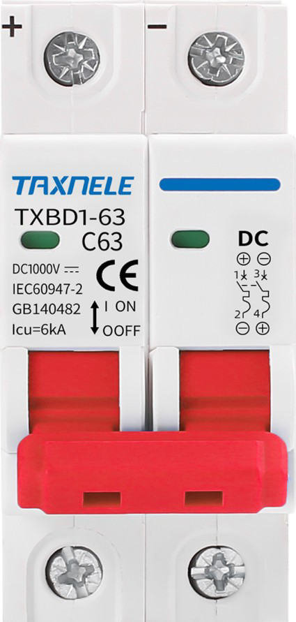
A DC Miniature Circuit Breaker (MCB) is a compact, automatic electrical switch designed to protect direct current (DC) circuits from overloads and short circuits. The "Red" designation typically indicates a specific current rating or application, making it easy to identify in electrical panels. DC MCBs are essential for ensuring the safety and reliability of DC power systems by interrupting the circuit when abnormal conditions are detected.
Explore Projects Built with DC MCB (Red)


Explore Projects Built with DC MCB (Red)
Common Applications and Use Cases
- Solar power systems and photovoltaic (PV) arrays
- Electric vehicle (EV) charging stations
- Battery banks and energy storage systems
- Industrial DC power distribution
- Telecommunications equipment
- DC motor protection in automation systems
Technical Specifications
Below are the key technical details for the DC MCB (Red):
| Parameter | Value |
|---|---|
| Rated Voltage | 12V DC, 24V DC, or 48V DC |
| Rated Current | 10A (typical for "Red" models) |
| Breaking Capacity | 6 kA |
| Number of Poles | 1P (Single Pole) |
| Tripping Curve | Type C (moderate inrush current) |
| Operating Temperature | -20°C to +70°C |
| Mounting Type | DIN Rail (35mm standard) |
| Housing Material | Flame-retardant thermoplastic |
| Dimensions (L x W x H) | 81mm x 18mm x 66mm |
| Compliance Standards | IEC 60947-2, IEC 60898-2 |
Pin Configuration and Descriptions
The DC MCB (Red) has two primary connection terminals:
| Terminal | Description |
|---|---|
| Line (Input) | Connects to the positive DC power source. |
| Load (Output) | Connects to the protected circuit or device. |
Usage Instructions
How to Use the DC MCB in a Circuit
- Mounting the MCB: Secure the DC MCB onto a 35mm DIN rail in your electrical panel.
- Wiring:
- Connect the positive DC power source to the Line (Input) terminal.
- Connect the protected circuit or load to the Load (Output) terminal.
- Ensure all connections are tight and secure to prevent arcing.
- Power On: Switch the MCB to the "ON" position to allow current flow.
- Testing: Test the MCB by simulating an overload or short circuit to ensure it trips correctly.
Important Considerations and Best Practices
- Voltage Rating: Ensure the MCB's rated voltage matches your DC system voltage.
- Current Rating: Use an MCB with a current rating appropriate for your load to avoid nuisance tripping or insufficient protection.
- Polarity: Maintain correct polarity when wiring the MCB, as DC circuits are polarity-sensitive.
- Environmental Conditions: Avoid installing the MCB in areas with excessive moisture, dust, or extreme temperatures.
- Regular Maintenance: Periodically inspect the MCB for signs of wear, damage, or loose connections.
Example: Connecting a DC MCB to an Arduino UNO
While DC MCBs are not directly connected to microcontrollers like the Arduino UNO, they can be used to protect the DC power supply feeding the Arduino. Below is an example of how to integrate a DC MCB into a circuit powering an Arduino UNO:
// Example: Arduino UNO powered by a DC power supply protected by a DC MCB
// Note: The DC MCB is placed between the power supply and the Arduino's VIN pin.

/*
  Circuit Description:
  - DC power supply (e.g., 12V DC) is connected to the Line terminal of the MCB.
  - The Load terminal of the MCB is connected to the Arduino's VIN pin.
  - The MCB protects the Arduino from overcurrent or short circuits.
*/

// No specific code is required for the MCB itself, as it operates independently.
// Ensure the MCB's current rating matches the Arduino's power requirements.
Troubleshooting and FAQs
Common Issues and Solutions
| Issue | Solution |
|---|---|
| MCB trips frequently without a clear cause. | Check for overload conditions or short circuits in the connected circuit. |
| MCB does not trip during a fault condition. | Verify the MCB's current rating and ensure it matches the load requirements. |
| Loose or overheating terminals. | Tighten all connections and inspect for signs of corrosion or damage. |
| MCB fails to reset after tripping. | Allow the MCB to cool down, then reset. Replace if the issue persists. |
FAQs
Can I use a DC MCB in an AC circuit?
- No, DC MCBs are specifically designed for direct current applications. Using them in AC circuits may result in improper operation or damage.
What does the "Red" color signify?
- The red color typically indicates a specific current rating (e.g., 10A) or application. Always refer to the manufacturer's datasheet for exact details.
How do I select the right DC MCB for my application?
- Consider the system voltage, load current, and breaking capacity. Ensure the MCB complies with relevant standards for your application.
Can I use a DC MCB to protect a battery bank?
- Yes, DC MCBs are commonly used to protect battery banks. Ensure the MCB's voltage and current ratings match the battery specifications.
By following this documentation, you can safely and effectively use the DC MCB (Red) in your DC power systems.