
How to Use battery with holder: Examples, Pinouts, and Specs
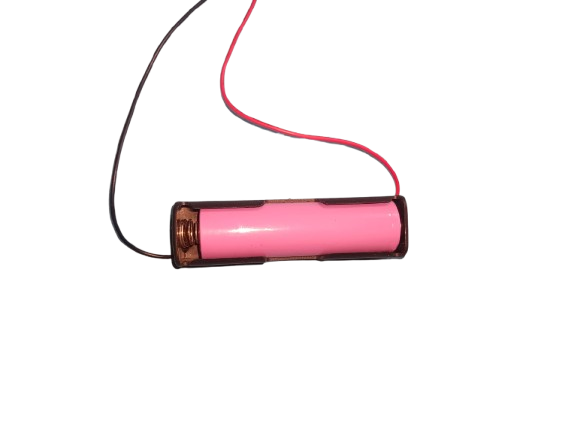
 Design with battery with holder in Cirkit Designer
Introduction
A battery holder is a device that securely holds one or more batteries in place, providing electrical connections to the battery terminals for powering electronic circuits. It is designed to ensure a stable and reliable connection while protecting the batteries from physical damage. Battery holders are available in various configurations to accommodate different battery sizes (e.g., AA, AAA, 9V, coin cells) and quantities.
Explore Projects Built with battery with holder
 Open Project in Cirkit Designer
 Open Project in Cirkit Designer
 Open Project in Cirkit Designer
 Open Project in Cirkit Designer
Explore Projects Built with battery with holder
Open Project in Cirkit DesignerOpen Project in Cirkit DesignerOpen Project in Cirkit DesignerOpen Project in Cirkit DesignerCommon Applications and Use Cases
- Powering portable electronic devices
- Prototyping and DIY electronics projects
- Robotics and embedded systems
- Backup power supplies
- Educational kits and experiments
Technical Specifications
The technical specifications of a battery holder depend on the type and size of the batteries it is designed to hold. Below is an example specification for a 2xAA battery holder with leads:
General Specifications
- Battery Type: AA (1.5V each)
- Number of Batteries: 2
- Output Voltage: 3V (when using two 1.5V AA batteries in series)
- Material: Plastic body with metal contacts
- Connection Type: Pre-soldered leads (red for positive, black for negative)
- Dimensions: 58mm x 30mm x 15mm (approx.)
Pin Configuration and Descriptions
| Pin/Lead | Description | Color Code |
|---|---|---|
| Positive | Connects to the positive terminal of the battery pack | Red |
| Negative | Connects to the negative terminal of the battery pack | Black |
Usage Instructions
How to Use the Component in a Circuit
- Insert Batteries: Place the batteries into the holder, ensuring correct polarity. Most holders have markings (+ and -) to guide proper insertion.
- Connect Leads:
- Connect the red lead (positive) to the positive terminal of your circuit.
- Connect the black lead (negative) to the ground (GND) of your circuit.
- Secure Connections: Use soldering, screw terminals, or a breadboard to ensure a stable connection.
- Power the Circuit: Once connected, the battery holder will supply power to your circuit.
Important Considerations and Best Practices
- Polarity: Always double-check the polarity of the batteries and connections to avoid damaging your circuit.
- Battery Type: Use the correct battery type and size specified for the holder.
- Current Rating: Ensure the batteries can supply sufficient current for your circuit's requirements.
- Avoid Short Circuits: Prevent the positive and negative leads from touching each other to avoid short circuits.
- Battery Life: Monitor battery voltage regularly to replace or recharge batteries as needed.
- Heat Management: Avoid overloading the circuit, as excessive current draw can cause the batteries to overheat.
Example: Connecting to an Arduino UNO
A battery holder can be used to power an Arduino UNO via its VIN pin. Below is an example:
Circuit Connection
- Connect the red lead (positive) of the battery holder to the VIN pin of the Arduino.
- Connect the black lead (negative) of the battery holder to the GND pin of the Arduino.
Sample Code
// Example code to blink an LED using an Arduino powered by a battery holder

const int ledPin = 13; // Pin connected to the onboard LED

void setup() {
  pinMode(ledPin, OUTPUT); // Set the LED pin as an output
}

void loop() {
  digitalWrite(ledPin, HIGH); // Turn the LED on
  delay(1000);               // Wait for 1 second
  digitalWrite(ledPin, LOW);  // Turn the LED off
  delay(1000);               // Wait for 1 second
}
Note: Ensure the battery pack provides a voltage within the Arduino's operating range (7-12V for VIN).
Troubleshooting and FAQs
Common Issues Users Might Face
No Power Output:
- Cause: Batteries inserted incorrectly or depleted.
- Solution: Check battery polarity and replace batteries if necessary.
Loose Connections:
- Cause: Leads not securely connected to the circuit.
- Solution: Ensure leads are firmly soldered or connected to terminals.
Overheating Batteries:
- Cause: Excessive current draw or short circuit.
- Solution: Verify the circuit's current requirements and check for short circuits.
Corrosion on Contacts:
- Cause: Prolonged exposure to moisture or leaking batteries.
- Solution: Clean contacts with isopropyl alcohol and replace damaged batteries.
FAQs
Q: Can I use rechargeable batteries with a battery holder?
A: Yes, as long as the rechargeable batteries match the holder's size and voltage requirements.Q: How do I know if my battery holder is compatible with my circuit?
A: Check the voltage and current requirements of your circuit and ensure the battery holder provides sufficient power.Q: Can I connect multiple battery holders in series or parallel?
A: Yes, you can connect holders in series to increase voltage or in parallel to increase capacity. Ensure proper wiring and polarity.Q: What should I do if the leads are too short?
A: Extend the leads using additional wires and soldering, ensuring proper insulation to prevent short circuits.