Cirkit Designer Logo
Cirkit Designer
Your all-in-one circuit design IDE
Home / 
Component Documentation

How to Use LED Strip: Examples, Pinouts, and Specs

Image of LED Strip
Cirkit Designer LogoDesign with LED Strip in Cirkit Designer

Introduction

An LED strip is a flexible circuit board populated with light-emitting diodes (LEDs) that illuminate when powered. These strips are versatile and can be used for various applications, including ambient lighting, accent lighting, task lighting, and even signage. They are popular in both residential and commercial settings due to their ease of installation, low power consumption, and customizable length.

Explore Projects Built with LED Strip

Use Cirkit Designer to design, explore, and prototype these projects online. Some projects support real-time simulation. Click "Open Project" to start designing instantly!
ESP32 and IRFZ44N MOSFET Controlled 12V LED Strip with Relay Module
Image of LED 12v PWM: A project utilizing LED Strip in a practical application
This circuit uses an ESP32 microcontroller to control the brightness and on/off state of a 12V LED strip. The brightness is adjusted via PWM signals sent to an IRFZ44N MOSFET, while a relay module is used to switch the LED strip on and off.
Cirkit Designer LogoOpen Project in Cirkit Designer
RGB LED Strip Color Controller with Potentiometers and Power Switch
Image of potbased decoration: A project utilizing LED Strip in a practical application
This circuit controls an RGB LED strip using three potentiometers, each potentiometer likely adjusts the intensity of one color channel (red, green, blue) of the LED strip. A rocker switch is used to power the circuit on and off, and an 18650 Li-Ion battery provides the power source. The common connection of the LED strip is connected to the negative terminal of the battery, while the positive terminal goes through the rocker switch to the potentiometers and then to the individual color channels.
Cirkit Designer LogoOpen Project in Cirkit Designer
Wi-Fi Controlled LED Strip with Wemos D1 Mini and IKEA Trådfri Driver
Image of WLED Diskbänken: A project utilizing LED Strip in a practical application
This circuit is designed to control a WS2812 RGB LED strip using a Wemos D1 Mini microcontroller running WLED software. The circuit includes an IKEA Trådfri LED driver that converts 24V to 5V via an LM2596 voltage regulator, and an nMOS transistor to switch the LED strip's ground connection. The setup is intended for lighting applications, such as under-cabinet lighting in a kitchen.
Cirkit Designer LogoOpen Project in Cirkit Designer
Arduino-Controlled RGB LED Strip Lighting System with 220V to 24V Power Transformer
Image of asd: A project utilizing LED Strip in a practical application
This circuit controls multiple RGB LED strips using an Arduino UNO, powered by a 220V to 24V transformer. The Arduino is programmed to turn the RGB LEDs on and off in a sequence, with each color channel (red, green, blue) connected to specific digital output pins on the Arduino.
Cirkit Designer LogoOpen Project in Cirkit Designer

Explore Projects Built with LED Strip

Use Cirkit Designer to design, explore, and prototype these projects online. Some projects support real-time simulation. Click "Open Project" to start designing instantly!
Image of LED 12v PWM: A project utilizing LED Strip in a practical application
ESP32 and IRFZ44N MOSFET Controlled 12V LED Strip with Relay Module
This circuit uses an ESP32 microcontroller to control the brightness and on/off state of a 12V LED strip. The brightness is adjusted via PWM signals sent to an IRFZ44N MOSFET, while a relay module is used to switch the LED strip on and off.
Cirkit Designer LogoOpen Project in Cirkit Designer
Image of potbased decoration: A project utilizing LED Strip in a practical application
RGB LED Strip Color Controller with Potentiometers and Power Switch
This circuit controls an RGB LED strip using three potentiometers, each potentiometer likely adjusts the intensity of one color channel (red, green, blue) of the LED strip. A rocker switch is used to power the circuit on and off, and an 18650 Li-Ion battery provides the power source. The common connection of the LED strip is connected to the negative terminal of the battery, while the positive terminal goes through the rocker switch to the potentiometers and then to the individual color channels.
Cirkit Designer LogoOpen Project in Cirkit Designer
Image of WLED Diskbänken: A project utilizing LED Strip in a practical application
Wi-Fi Controlled LED Strip with Wemos D1 Mini and IKEA Trådfri Driver
This circuit is designed to control a WS2812 RGB LED strip using a Wemos D1 Mini microcontroller running WLED software. The circuit includes an IKEA Trådfri LED driver that converts 24V to 5V via an LM2596 voltage regulator, and an nMOS transistor to switch the LED strip's ground connection. The setup is intended for lighting applications, such as under-cabinet lighting in a kitchen.
Cirkit Designer LogoOpen Project in Cirkit Designer
Image of asd: A project utilizing LED Strip in a practical application
Arduino-Controlled RGB LED Strip Lighting System with 220V to 24V Power Transformer
This circuit controls multiple RGB LED strips using an Arduino UNO, powered by a 220V to 24V transformer. The Arduino is programmed to turn the RGB LEDs on and off in a sequence, with each color channel (red, green, blue) connected to specific digital output pins on the Arduino.
Cirkit Designer LogoOpen Project in Cirkit Designer

Technical Specifications

Key Technical Details

  • Voltage Range: Typically 5V, 12V, or 24V DC
  • Current Consumption: Varies depending on the number of LEDs per meter and type
  • Power Rating: Usually expressed in watts per meter (W/m)
  • LED Density: Number of LEDs per meter (e.g., 30, 60, 120 LEDs/m)
  • Color Options: Single color, RGB (Red, Green, Blue), RGBW (RGB + White), tunable white, etc.
  • Luminous Flux: Measured in lumens per meter (lm/m)
  • Color Temperature: For white LEDs, typically ranging from 2700K (warm white) to 6500K (cool white)
  • IP Rating: Indicates the level of protection against solids and liquids (e.g., IP20, IP65, IP67)

Pin Configuration and Descriptions

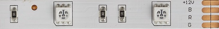
The pin configuration for LED strips can vary depending on the type (single color, RGB, RGBW, etc.). Below is an example of a common RGB LED strip pinout:

Pin Number Description
1 12V or 24V Power
2 Red Control
3 Green Control
4 Blue Control
5 Ground (optional)

Usage Instructions

How to Use the LED Strip in a Circuit

  1. Power Supply: Choose a power supply that matches the voltage and can provide sufficient current for the length of the LED strip you are using.
  2. Connecting: Connect the positive terminal of the power supply to the V+ pad on the LED strip, and the negative terminal to the GND pad.
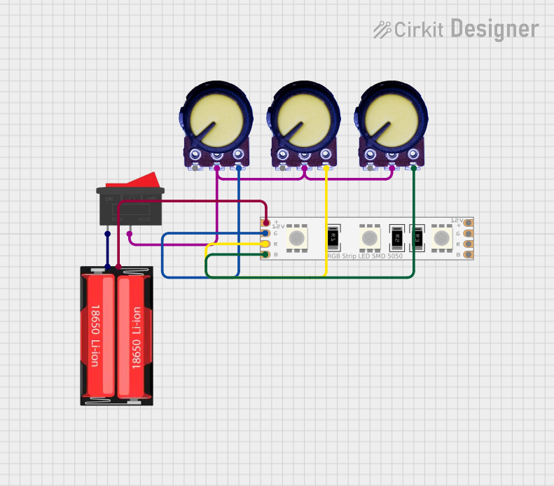
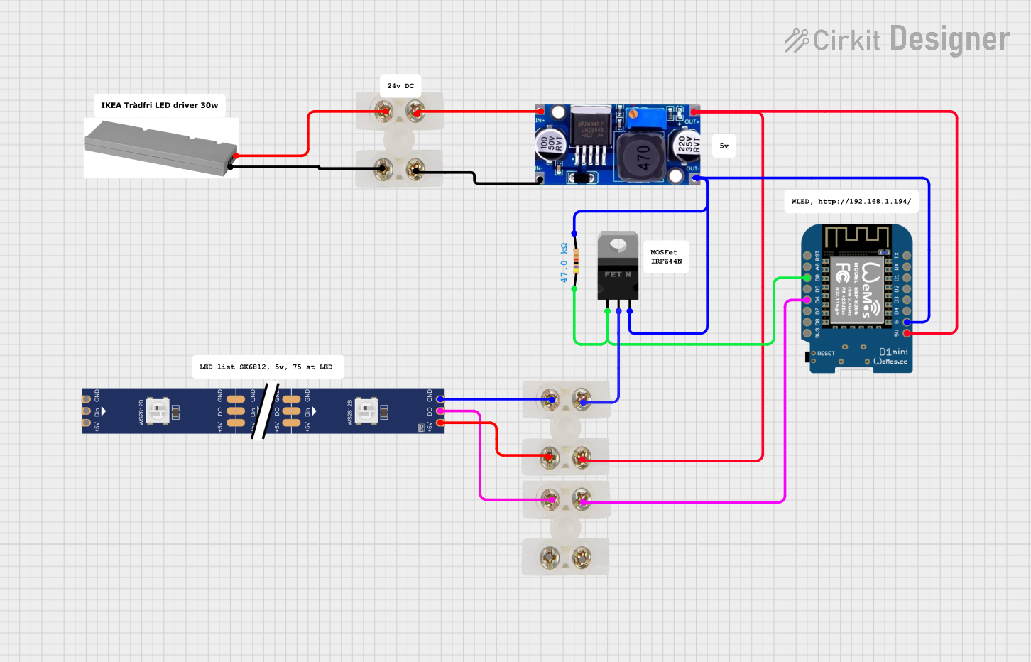
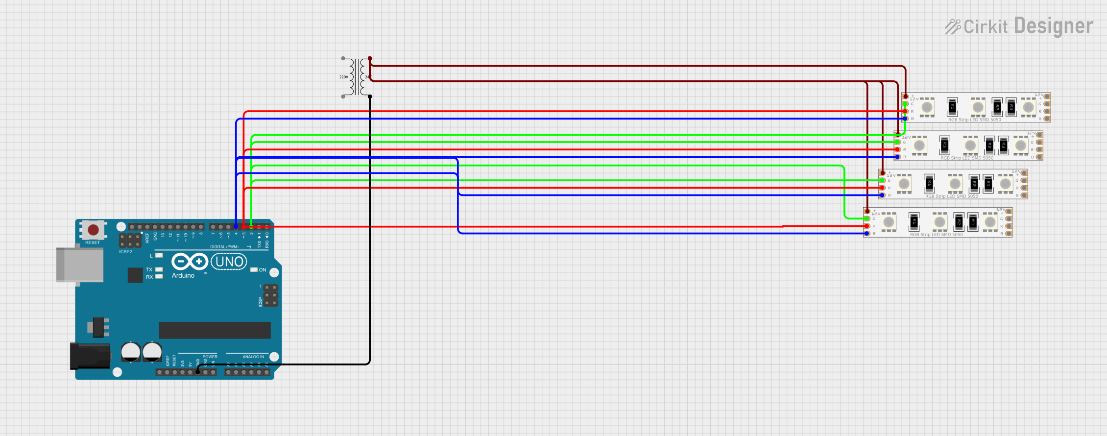
  3. Controlling Brightness/Color: For RGB strips, use a controller to adjust colors and brightness. This can be a dedicated LED controller or a microcontroller like an Arduino.
  4. Cutting: LED strips can be cut at designated points, usually marked with a line and scissors icon, to fit the desired length.
  5. Mounting: Use the adhesive backing to mount the strip to a clean, dry surface. For non-adhesive strips, use mounting clips.

Important Considerations and Best Practices

  • Heat Dissipation: Ensure adequate ventilation around the LED strip to prevent overheating.
  • Voltage Drop: For long runs of LED strips, be aware of voltage drop which can cause the LEDs at the end of the strip to appear dimmer.
  • Waterproofing: If using in a moist environment, select an LED strip with an appropriate IP rating and seal connections properly.

Troubleshooting and FAQs

Common Issues

  • LEDs Not Lighting Up: Check power supply and connections. Ensure the polarity is correct.
  • Dim LEDs: This could be due to voltage drop or an underpowered supply. Consider using a higher current power supply or adding additional power injection points along the strip.
  • Flickering LEDs: This may be caused by loose connections, inadequate power supply, or a faulty controller.

Solutions and Tips for Troubleshooting

  • Check Connections: Ensure all connections are secure and properly soldered or connected.
  • Power Supply: Verify that the power supply is functioning and providing the correct voltage.
  • Controller Issues: If using a microcontroller, ensure the code is correct and the controller is functioning properly.

Example Arduino Code for Controlling an RGB LED Strip

#include <Adafruit_NeoPixel.h>

#define LED_PIN     6 // The pin where the LED strip is connected
#define LED_COUNT  30 // Number of LEDs in the strip

// Initialize the LED strip
Adafruit_NeoPixel strip(LED_COUNT, LED_PIN, NEO_GRB + NEO_KHZ800);

void setup() {
  strip.begin(); // Initialize the strip
  strip.show();  // Initialize all pixels to 'off'
}

void loop() {
  // Set the first pixel to red color (R, G, B)
  strip.setPixelColor(0, strip.Color(255, 0, 0)); 
  strip.show(); // Update the strip with new settings
  delay(500); // Wait for half a second

  // Turn off the first pixel
  strip.setPixelColor(0, strip.Color(0, 0, 0));
  strip.show();
  delay(500);
}

Note: The above code uses the Adafruit NeoPixel library to control an RGB LED strip connected to an Arduino UNO. Ensure that the LED_PIN and LED_COUNT are set to match your specific setup. The strip.Color() function takes three arguments corresponding to the red, green, and blue components of the color, each ranging from 0 to 255.