How to Use rocker switch: Examples, Pinouts, and Specs
Introduction
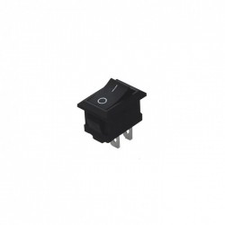
A rocker switch is a type of on/off switch that toggles between two positions, resembling a seesaw motion. It is named for its rocking mechanism, which allows users to press one side to close the circuit (on) and the other to open it (off). Rocker switches are widely used in various applications, including household appliances, automotive, industrial controls, and consumer electronics, due to their ease of use and reliability.
Explore Projects Built with rocker switch
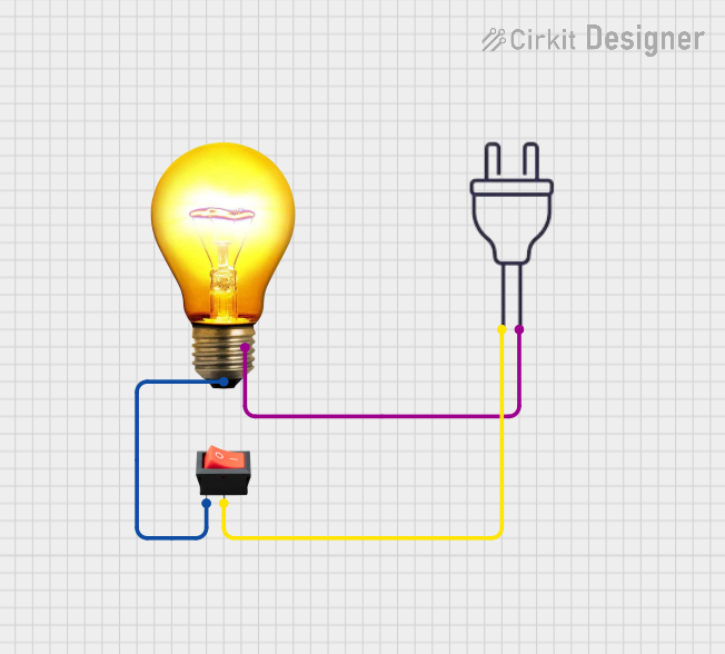


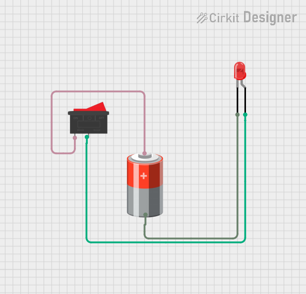
Explore Projects Built with rocker switch
Technical Specifications
General Characteristics
- Switch Type: Rocker
- Action: SPST (Single Pole, Single Throw) or DPST (Double Pole, Single Throw), etc.
- Current Rating: Typically ranges from 3A to 20A
- Voltage Rating: Commonly rated for 120V or 250V AC
- Contact Resistance: Specified in milliohms (mΩ)
- Insulation Resistance: Specified in megaohms (MΩ)
- Dielectric Strength: Voltage that the switch can withstand without breakdown
- Operating Temperature Range: Usually from -20°C to +85°C
- Mechanical Life: Number of actuations (e.g., 50,000 cycles)
- Termination Type: Solder lugs, quick connect, or PCB pins
Pin Configuration and Descriptions
| Pin Number | Description | Note |
|---|---|---|
| 1 | Input/Line Terminal | Connects to the power source |
| 2 | Output/Load Terminal | Connects to the device being powered |
| 3 | Ground Terminal | Only present in illuminated switches |
Note: The pin configuration may vary depending on the type of rocker switch (e.g., SPST, SPDT, DPDT). The above table is for a basic SPST rocker switch.
Usage Instructions
Wiring the Rocker Switch
- Power Off: Ensure all power sources are turned off before wiring the switch to prevent electric shock.
- Identify Terminals: Locate the input and output terminals on the rocker switch.
- Connect Power Source: Attach the live wire from the power source to the input terminal (Pin 1).
- Connect Load: Attach the wire leading to the device or load to the output terminal (Pin 2).
- Grounding (if applicable): If the switch is illuminated or requires grounding, connect the ground wire to the ground terminal (Pin 3).
Best Practices
- Use a rocker switch with a current and voltage rating that matches or exceeds the requirements of the application.
- Ensure that all connections are secure and that there is no risk of short circuits.
- If the switch is to be panel-mounted, make sure the cutout dimensions are accurate for a proper fit.
- For illuminated switches, ensure the lighting voltage matches the circuit voltage.
Troubleshooting and FAQs
Common Issues
- Switch Does Not Operate: Check for loose connections or a blown fuse. Ensure the power source is functional.
- Illuminated Switch Not Lighting Up: Verify that the ground connection is secure and that the bulb or LED is functional.
- Intermittent Operation: Inspect for any signs of damage or wear. Mechanical life may be exceeded.
FAQs
Q: Can I use a rocker switch with a higher rating than needed? A: Yes, using a switch with a higher rating is generally safe. However, it should not be lower than the circuit's requirements.
Q: Are rocker switches suitable for outdoor use? A: Unless specifically rated for outdoor or waterproof applications, standard rocker switches should be used indoors.
Q: How do I know if my rocker switch is on or off? A: Many rocker switches have an "I" and "O" symbol to indicate the on and off positions, respectively.
Example Arduino UNO Code
This example demonstrates how to use a rocker switch to control an LED with an Arduino UNO.
// Define the pin numbers
const int ledPin = 13;       // LED connected to digital pin 13
const int switchPin = 7;     // Rocker switch connected to digital pin 7

void setup() {
  pinMode(ledPin, OUTPUT);   // Set the LED pin as an output
  pinMode(switchPin, INPUT); // Set the switch pin as an input
}

void loop() {
  // Read the state of the rocker switch
  int switchState = digitalRead(switchPin);

  // Turn the LED on if the switch is in the 'on' position
  if (switchState == HIGH) {
    digitalWrite(ledPin, HIGH);
  } else {
    digitalWrite(ledPin, LOW);
  }
}
Note: Ensure that the rocker switch is connected to the switchPin with appropriate pull-up or pull-down resistors as needed.
This documentation provides a comprehensive overview of the rocker switch, its technical specifications, usage instructions, and troubleshooting tips. It also includes an example code snippet for interfacing with an Arduino UNO, which can be adapted to various other microcontroller platforms.