How to Use Battery Capacity Monitor: Examples, Pinouts, and Specs
Introduction
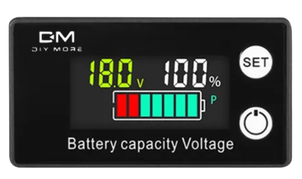
The Battery Capacity Monitor is a device designed to measure and display the remaining charge in a battery. It provides real-time information about the battery's state of charge, helping users assess its health and performance. This component is widely used in portable electronics, renewable energy systems, electric vehicles, and backup power systems to ensure efficient battery usage and prevent over-discharge or overcharging.
Explore Projects Built with Battery Capacity Monitor
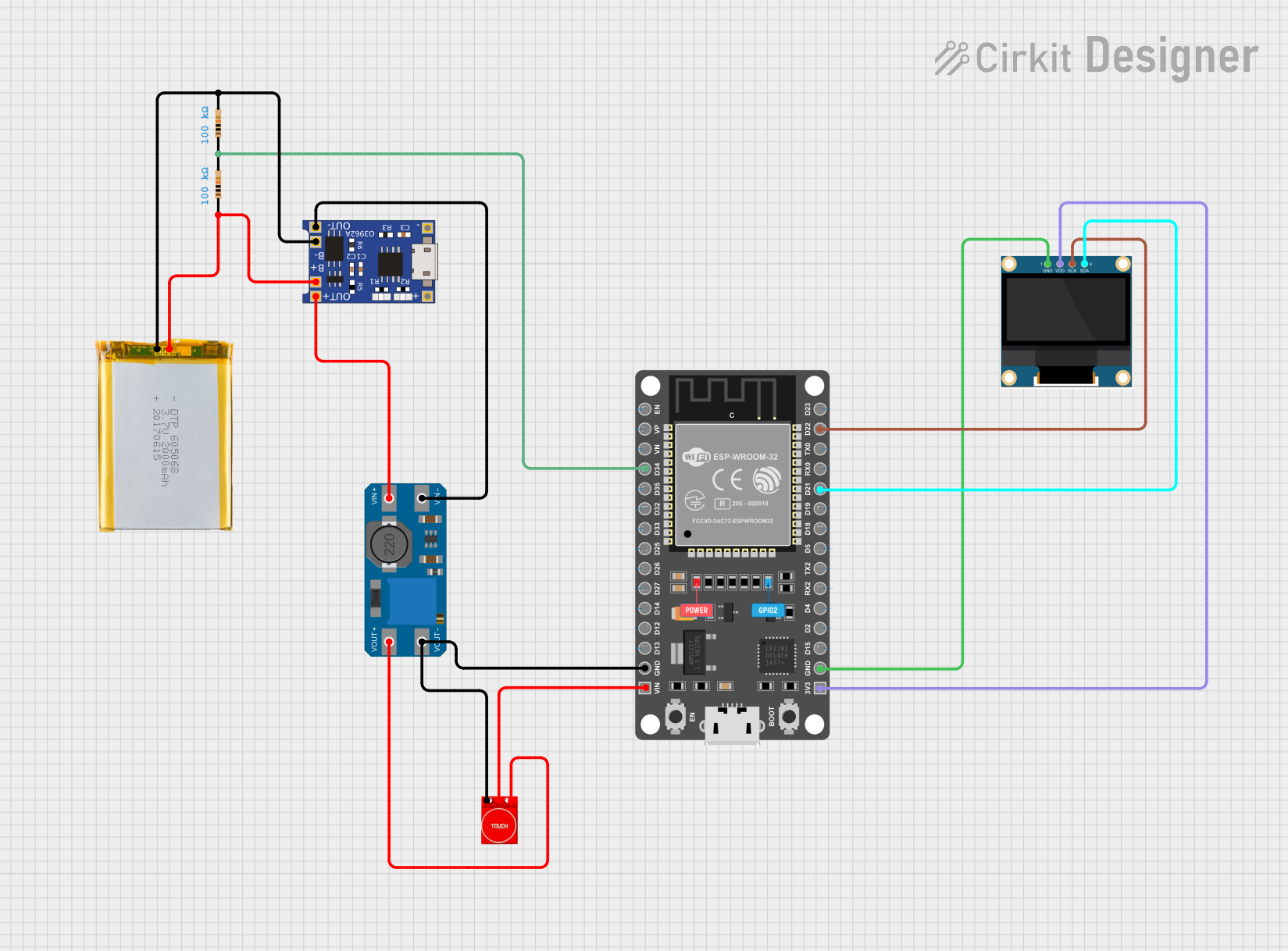
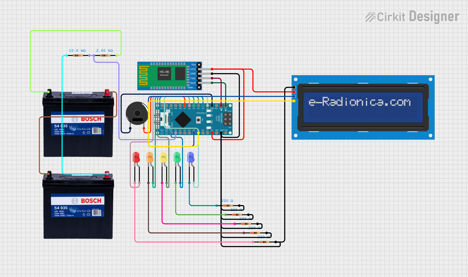
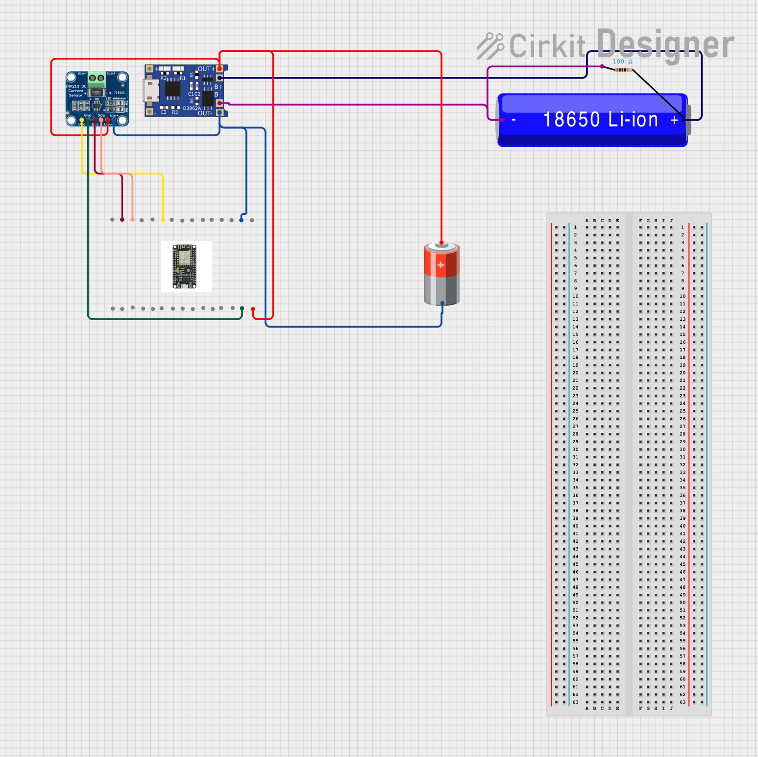

Explore Projects Built with Battery Capacity Monitor
Common Applications
- Monitoring battery levels in solar power systems
- Assessing charge in electric vehicles and e-bikes
- Portable power banks and UPS systems
- Battery-powered tools and devices
Technical Specifications
Below are the key technical details of the Battery Capacity Monitor:
| Parameter | Value |
|---|---|
| Operating Voltage | 3.7V - 30V DC |
| Current Consumption | ≤ 20mA |
| Display Type | LCD/LED (varies by model) |
| Measurement Accuracy | ±1% |
| Supported Battery Types | Lithium-ion, Lead-acid, NiMH, etc. |
| Operating Temperature | -10°C to 60°C |
| Dimensions | Varies by model (e.g., 48x29x21mm) |
Pin Configuration
The Battery Capacity Monitor typically has the following pin configuration:
| Pin Name | Description |
|---|---|
| V+ | Positive terminal for power input |
| V- | Negative terminal for power input (ground) |
| B+ | Positive terminal for battery connection |
| B- | Negative terminal for battery connection |
| COM | Communication pin (optional, for advanced models) |
Usage Instructions
How to Use the Battery Capacity Monitor
- Connect the Power Supply:
- Connect the
V+andV-pins to a DC power source within the operating voltage range (e.g., 5V or 12V).
- Connect the
- Connect the Battery:
- Attach the
B+andB-pins to the positive and negative terminals of the battery, respectively.
- Attach the
- Mount the Display:
- If the monitor has a detachable display, mount it in a visible location for easy reading.
- Power On:
- Once connected, the monitor will automatically display the battery's remaining capacity as a percentage or voltage reading.
Important Considerations
- Voltage Compatibility: Ensure the monitor's voltage range matches the battery's voltage.
- Battery Type: Configure the monitor (if applicable) to match the type of battery being used (e.g., lithium-ion or lead-acid).
- Wiring: Double-check all connections to avoid short circuits or incorrect readings.
- Calibration: Some monitors may require calibration for accurate readings. Refer to the manufacturer's instructions for details.
Example: Using with Arduino UNO
For advanced models with a communication pin (COM), you can interface the Battery Capacity Monitor with an Arduino UNO to log battery data. Below is an example code snippet:
// Example code to read battery data from a Battery Capacity Monitor
// connected to an Arduino UNO via the COM pin.

#include <SoftwareSerial.h>

// Define the COM pin for communication
#define COM_PIN 10

// Initialize SoftwareSerial for communication
SoftwareSerial batteryMonitor(COM_PIN, -1); // RX pin only, no TX needed

void setup() {
  Serial.begin(9600); // Start serial communication with the PC
  batteryMonitor.begin(9600); // Start communication with the monitor

  Serial.println("Battery Capacity Monitor Initialized");
}

void loop() {
  if (batteryMonitor.available()) {
    String batteryData = batteryMonitor.readStringUntil('\n');
    // Read data from the monitor until a newline character is received

    Serial.print("Battery Data: ");
    Serial.println(batteryData); // Print the received data to the Serial Monitor
  }

  delay(1000); // Wait for 1 second before reading again
}
Note: Ensure the Battery Capacity Monitor supports serial communication and is configured to output data via the COM pin.
Troubleshooting and FAQs
Common Issues
No Display or Incorrect Readings:
- Cause: Incorrect wiring or incompatible voltage.
- Solution: Verify all connections and ensure the battery voltage is within the monitor's supported range.
Flickering Display:
- Cause: Insufficient power supply or loose connections.
- Solution: Check the power source and secure all connections.
Inaccurate Readings:
- Cause: Monitor not calibrated for the specific battery type.
- Solution: Calibrate the monitor as per the manufacturer's instructions.
No Data Output on Arduino:
- Cause: Incorrect baud rate or wiring.
- Solution: Ensure the baud rate matches the monitor's specifications and check the
COMpin connection.
FAQs
Q: Can this monitor be used with a 24V lead-acid battery?
- A: Yes, as long as the monitor's voltage range supports 24V systems.
Q: Does the monitor support multiple batteries in series?
- A: It depends on the model. Check the specifications to ensure compatibility with series configurations.
Q: How do I reset the monitor?
- A: Most monitors have a reset button or require a power cycle to reset. Refer to the user manual for specific instructions.
Q: Can I use this monitor outdoors?
- A: Only if the monitor is rated for outdoor use. Check the IP rating for water and dust resistance.
By following this documentation, you can effectively integrate and troubleshoot the Battery Capacity Monitor in your projects.