Cirkit Designer Logo
Cirkit Designer
Your all-in-one circuit design IDE
Home / 
Component Documentation

How to Use Digital Compass: Examples, Pinouts, and Specs

Image of Digital Compass
Cirkit Designer LogoDesign with Digital Compass in Cirkit Designer

Introduction

The Grove Digital Compass is an electronic device designed to determine direction relative to the Earth's magnetic field. It utilizes magnetic sensors to provide accurate heading information, making it an essential component for navigation, orientation, and robotics applications. This compact and reliable module is ideal for projects requiring precise directional data.

Explore Projects Built with Digital Compass

Use Cirkit Designer to design, explore, and prototype these projects online. Some projects support real-time simulation. Click "Open Project" to start designing instantly!
Arduino Nano-Based Portable GSM-GPS Navigator with Compass and Stepper Motor Control
Image of Compass: A project utilizing Digital Compass in a practical application
This circuit features an Arduino Nano microcontroller coordinating communication, navigation, and motion control functions. It includes modules for GSM, GPS, and digital compass capabilities, as well as a stepper motor for precise movement, all powered by a LiPo battery with voltage regulation.
Cirkit Designer LogoOpen Project in Cirkit Designer
Satellite Compass and Network-Integrated GPS Data Processing System
Image of GPS 시스템 측정 구성도_241016: A project utilizing Digital Compass in a practical application
This circuit comprises a satellite compass, a mini PC, two GPS antennas, power supplies, a network switch, media converters, and an atomic rubidium clock. The satellite compass is powered by a triple output DC power supply and interfaces with an RS232 splitter for 1PPS signals. The mini PCs are connected to the USRP B200 devices via USB for data and power, and to media converters via Ethernet, which in turn connect to a network switch using fiber optic links. The antennas are connected to the USRP B200s through RF directional couplers, and the atomic clock provides a 1PPS input to the RS232 splitter.
Cirkit Designer LogoOpen Project in Cirkit Designer
Arduino Mega 2560 Controlled Robot with Bluetooth, GPS, Ultrasonic Sensing, and Compass Navigation
Image of SkripsieDiagram: A project utilizing Digital Compass in a practical application
This circuit features an Arduino Mega 2560 microcontroller interfaced with a Bluetooth HC-06 module for wireless communication, a GPS NEO 6M module for location tracking, an HC-SR04 ultrasonic sensor for distance measurement, and an HMC5883L compass module for magnetic heading detection. It also includes a L293D motor driver to control two DC motors, powered by a 12v battery. The Arduino coordinates the sensors and Bluetooth communication, as well as controls the motors based on the received data and sensor inputs.
Cirkit Designer LogoOpen Project in Cirkit Designer
Raspberry Pi Pico-Based Bluetooth Compass
Image of sat_dish: compass-intro: A project utilizing Digital Compass in a practical application
This circuit features a Raspberry Pi Pico microcontroller interfaced with an HC-05 Bluetooth module and an HMC5883L digital compass. The Pico's GPIO pins are configured for serial communication with the HC-05 (TX/RX) and I2C communication with the HMC5883L (SCL/SDA). The circuit is likely designed for wireless data transmission of compass readings.
Cirkit Designer LogoOpen Project in Cirkit Designer

Explore Projects Built with Digital Compass

Use Cirkit Designer to design, explore, and prototype these projects online. Some projects support real-time simulation. Click "Open Project" to start designing instantly!
Image of Compass: A project utilizing Digital Compass in a practical application
Arduino Nano-Based Portable GSM-GPS Navigator with Compass and Stepper Motor Control
This circuit features an Arduino Nano microcontroller coordinating communication, navigation, and motion control functions. It includes modules for GSM, GPS, and digital compass capabilities, as well as a stepper motor for precise movement, all powered by a LiPo battery with voltage regulation.
Cirkit Designer LogoOpen Project in Cirkit Designer
Image of GPS 시스템 측정 구성도_241016: A project utilizing Digital Compass in a practical application
Satellite Compass and Network-Integrated GPS Data Processing System
This circuit comprises a satellite compass, a mini PC, two GPS antennas, power supplies, a network switch, media converters, and an atomic rubidium clock. The satellite compass is powered by a triple output DC power supply and interfaces with an RS232 splitter for 1PPS signals. The mini PCs are connected to the USRP B200 devices via USB for data and power, and to media converters via Ethernet, which in turn connect to a network switch using fiber optic links. The antennas are connected to the USRP B200s through RF directional couplers, and the atomic clock provides a 1PPS input to the RS232 splitter.
Cirkit Designer LogoOpen Project in Cirkit Designer
Image of SkripsieDiagram: A project utilizing Digital Compass in a practical application
Arduino Mega 2560 Controlled Robot with Bluetooth, GPS, Ultrasonic Sensing, and Compass Navigation
This circuit features an Arduino Mega 2560 microcontroller interfaced with a Bluetooth HC-06 module for wireless communication, a GPS NEO 6M module for location tracking, an HC-SR04 ultrasonic sensor for distance measurement, and an HMC5883L compass module for magnetic heading detection. It also includes a L293D motor driver to control two DC motors, powered by a 12v battery. The Arduino coordinates the sensors and Bluetooth communication, as well as controls the motors based on the received data and sensor inputs.
Cirkit Designer LogoOpen Project in Cirkit Designer
Image of sat_dish: compass-intro: A project utilizing Digital Compass in a practical application
Raspberry Pi Pico-Based Bluetooth Compass
This circuit features a Raspberry Pi Pico microcontroller interfaced with an HC-05 Bluetooth module and an HMC5883L digital compass. The Pico's GPIO pins are configured for serial communication with the HC-05 (TX/RX) and I2C communication with the HMC5883L (SCL/SDA). The circuit is likely designed for wireless data transmission of compass readings.
Cirkit Designer LogoOpen Project in Cirkit Designer

Common Applications and Use Cases

  • Navigation systems for drones, robots, and vehicles
  • Orientation tracking in wearable devices
  • Geographic positioning and mapping
  • Educational projects and prototyping with microcontrollers (e.g., Arduino)

Technical Specifications

The following table outlines the key technical details of the Grove Digital Compass:

Parameter Specification
Operating Voltage 3.3V to 5V
Operating Current < 10mA
Communication Protocol I2C
Measurement Range 360° (full circle)
Accuracy ±1° to ±2°
Dimensions 20mm x 20mm
Operating Temperature -40°C to 85°C

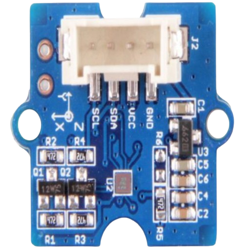
Pin Configuration and Descriptions

The Grove Digital Compass features a 4-pin interface for easy connection. The pinout is as follows:

Pin Name Description
1 VCC Power supply input (3.3V to 5V)
2 GND Ground connection
3 SDA I2C data line for communication
4 SCL I2C clock line for communication

Usage Instructions

How to Use the Component in a Circuit

  1. Connect the Module: Use a Grove cable to connect the Digital Compass to an I2C port on a compatible microcontroller, such as an Arduino UNO.
  2. Power the Module: Ensure the module is powered with a voltage between 3.3V and 5V.
  3. Install Required Libraries: For Arduino, install the necessary I2C and compass libraries (e.g., Wire.h and Adafruit_Sensor).
  4. Write and Upload Code: Use the provided example code to read heading data from the compass.

Important Considerations and Best Practices

  • Avoid Magnetic Interference: Keep the module away from strong magnetic fields or ferromagnetic materials, as they can distort readings.
  • Calibrate the Compass: Perform a calibration routine to ensure accurate measurements, especially in new environments.
  • Use Proper Pull-Up Resistors: If not already included, add pull-up resistors (typically 4.7kΩ) on the SDA and SCL lines for stable I2C communication.
  • Check I2C Address: The default I2C address of the module is typically 0x1E, but consult the datasheet to confirm.

Example Code for Arduino UNO

Below is an example Arduino sketch to read heading data from the Grove Digital Compass:

#include <Wire.h> // Include the Wire library for I2C communication

#define COMPASS_ADDRESS 0x1E // Default I2C address of the compass

void setup() {
  Serial.begin(9600); // Initialize serial communication at 9600 baud
  Wire.begin();       // Initialize I2C communication
  initializeCompass(); // Call function to configure the compass
}

void loop() {
  float heading = readHeading(); // Read the compass heading
  Serial.print("Heading: ");
  Serial.print(heading);
  Serial.println("°"); // Print the heading in degrees
  delay(500); // Wait for 500ms before the next reading
}

void initializeCompass() {
  Wire.beginTransmission(COMPASS_ADDRESS); // Start communication with compass
  Wire.write(0x00); // Select configuration register A
  Wire.write(0x70); // Set measurement mode to normal
  Wire.endTransmission();

  Wire.beginTransmission(COMPASS_ADDRESS);
  Wire.write(0x02); // Select mode register
  Wire.write(0x00); // Set continuous measurement mode
  Wire.endTransmission();
}

float readHeading() {
  Wire.beginTransmission(COMPASS_ADDRESS);
  Wire.write(0x03); // Select data output register
  Wire.endTransmission();

  Wire.requestFrom(COMPASS_ADDRESS, 6); // Request 6 bytes of data
  if (Wire.available() == 6) {
    int16_t x = (Wire.read() << 8) | Wire.read(); // Read X-axis data
    int16_t z = (Wire.read() << 8) | Wire.read(); // Read Z-axis data
    int16_t y = (Wire.read() << 8) | Wire.read(); // Read Y-axis data

    // Calculate heading in degrees
    float heading = atan2((float)y, (float)x) * 180 / PI;
    if (heading < 0) heading += 360; // Ensure heading is positive
    return heading;
  }
  return 0; // Return 0 if no data is available
}

Troubleshooting and FAQs

Common Issues and Solutions

  1. No Data or Incorrect Readings

    • Cause: Loose connections or incorrect wiring.
    • Solution: Verify all connections, ensuring SDA and SCL are connected to the correct pins on the microcontroller.
  2. Inconsistent or Fluctuating Readings

    • Cause: Magnetic interference or lack of calibration.
    • Solution: Move the module away from magnetic sources and perform a calibration routine.
  3. I2C Communication Failure

    • Cause: Incorrect I2C address or missing pull-up resistors.
    • Solution: Check the module's I2C address and ensure pull-up resistors are in place.

FAQs

  • Q: Can I use this module with a Raspberry Pi?

    • A: Yes, the Grove Digital Compass is compatible with Raspberry Pi via the I2C interface. Use libraries like smbus for Python.
  • Q: How do I calibrate the compass?

    • A: Rotate the module in all directions to map the magnetic field. Some libraries include built-in calibration functions.
  • Q: What is the maximum cable length for I2C communication?

    • A: The maximum length depends on the pull-up resistor values and communication speed, but it is typically limited to 1 meter for reliable operation.

This documentation provides a comprehensive guide to using the Grove Digital Compass effectively in your projects.