Cirkit Designer Logo
Cirkit Designer
Your all-in-one circuit design IDE
Home / 
Component Documentation

How to Use Seeed Studio XIAO RP2040: Examples, Pinouts, and Specs

Image of Seeed Studio XIAO RP2040
Cirkit Designer LogoDesign with Seeed Studio XIAO RP2040 in Cirkit Designer

Introduction

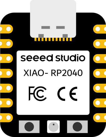
The Seeed Studio XIAO RP2040 is a compact and versatile microcontroller board powered by the Raspberry Pi RP2040 chip. It features dual-core ARM Cortex-M0+ processors, 264KB of SRAM, and 2MB of onboard flash memory. Designed for low-power applications, the XIAO RP2040 is ideal for projects requiring a small form factor, high performance, and easy integration.

Explore Projects Built with Seeed Studio XIAO RP2040

Use Cirkit Designer to design, explore, and prototype these projects online. Some projects support real-time simulation. Click "Open Project" to start designing instantly!
I2C-Controlled OLED Display with External EEPROM and Interactive Pushbuttons
Image of godmode: A project utilizing Seeed Studio XIAO RP2040 in a practical application
This is a microcontroller-based interactive device featuring a Wemos D1 Mini, an OLED display, external EEPROM, and an I/O expander. It includes user input buttons and status LEDs, with potential MIDI interface capabilities.
Cirkit Designer LogoOpen Project in Cirkit Designer
ESP32-Based Multi-Sensor Health Monitoring System with Bluetooth Connectivity
Image of circuit diagram: A project utilizing Seeed Studio XIAO RP2040 in a practical application
This circuit features an ESP32-WROOM-32UE microcontroller as the central processing unit, interfacing with a variety of sensors and modules. It includes a MAX30100 pulse oximeter and heart-rate sensor, an MLX90614 infrared thermometer, an HC-05 Bluetooth module for wireless communication, and a Neo 6M GPS module for location tracking. All components are powered by a common voltage supply and are connected to specific GPIO pins on the ESP32 for data exchange, with the sensors using I2C communication and the modules using UART.
Cirkit Designer LogoOpen Project in Cirkit Designer
Dual Microcontroller Integration with Arduino Micro Pro and RP2040 Zero for Enhanced I/O Control
Image of RP2040MacroKey: A project utilizing Seeed Studio XIAO RP2040 in a practical application
This circuit integrates an Arduino Micro Pro and an RP2040 Zero microcontroller, interconnected to share power and ground, as well as several GPIO pins. The RP2040 Zero is programmed with a basic setup and loop structure, indicating it is ready for further development. The design suggests a collaborative processing or sensor data sharing application between the two microcontrollers.
Cirkit Designer LogoOpen Project in Cirkit Designer
Battery-Powered Smart Light with Proximity Sensor and OLED Display using Adafruit QT Py RP2040
Image of lab: A project utilizing Seeed Studio XIAO RP2040 in a practical application
This circuit is a portable, battery-powered system featuring an Adafruit QT Py RP2040 microcontroller that interfaces with an OLED display, a proximity sensor, an accelerometer, and an RGB LED strip. The system is powered by a lithium-ion battery with a step-up boost converter to provide 5V for the LED strip, and it includes a toggle switch for power control. The microcontroller communicates with the sensors and display via I2C.
Cirkit Designer LogoOpen Project in Cirkit Designer

Explore Projects Built with Seeed Studio XIAO RP2040

Use Cirkit Designer to design, explore, and prototype these projects online. Some projects support real-time simulation. Click "Open Project" to start designing instantly!
Image of godmode: A project utilizing Seeed Studio XIAO RP2040 in a practical application
I2C-Controlled OLED Display with External EEPROM and Interactive Pushbuttons
This is a microcontroller-based interactive device featuring a Wemos D1 Mini, an OLED display, external EEPROM, and an I/O expander. It includes user input buttons and status LEDs, with potential MIDI interface capabilities.
Cirkit Designer LogoOpen Project in Cirkit Designer
Image of circuit diagram: A project utilizing Seeed Studio XIAO RP2040 in a practical application
ESP32-Based Multi-Sensor Health Monitoring System with Bluetooth Connectivity
This circuit features an ESP32-WROOM-32UE microcontroller as the central processing unit, interfacing with a variety of sensors and modules. It includes a MAX30100 pulse oximeter and heart-rate sensor, an MLX90614 infrared thermometer, an HC-05 Bluetooth module for wireless communication, and a Neo 6M GPS module for location tracking. All components are powered by a common voltage supply and are connected to specific GPIO pins on the ESP32 for data exchange, with the sensors using I2C communication and the modules using UART.
Cirkit Designer LogoOpen Project in Cirkit Designer
Image of RP2040MacroKey: A project utilizing Seeed Studio XIAO RP2040 in a practical application
Dual Microcontroller Integration with Arduino Micro Pro and RP2040 Zero for Enhanced I/O Control
This circuit integrates an Arduino Micro Pro and an RP2040 Zero microcontroller, interconnected to share power and ground, as well as several GPIO pins. The RP2040 Zero is programmed with a basic setup and loop structure, indicating it is ready for further development. The design suggests a collaborative processing or sensor data sharing application between the two microcontrollers.
Cirkit Designer LogoOpen Project in Cirkit Designer
Image of lab: A project utilizing Seeed Studio XIAO RP2040 in a practical application
Battery-Powered Smart Light with Proximity Sensor and OLED Display using Adafruit QT Py RP2040
This circuit is a portable, battery-powered system featuring an Adafruit QT Py RP2040 microcontroller that interfaces with an OLED display, a proximity sensor, an accelerometer, and an RGB LED strip. The system is powered by a lithium-ion battery with a step-up boost converter to provide 5V for the LED strip, and it includes a toggle switch for power control. The microcontroller communicates with the sensors and display via I2C.
Cirkit Designer LogoOpen Project in Cirkit Designer

Common Applications and Use Cases

  • Wearable devices and IoT applications
  • Robotics and automation systems
  • Prototyping and educational projects
  • Low-power data logging and sensor interfacing
  • Compact DIY electronics projects

Technical Specifications

Key Technical Details

Specification Value
Microcontroller Raspberry Pi RP2040
Processor Dual-core ARM Cortex-M0+
Clock Speed Up to 133 MHz
SRAM 264 KB
Flash Memory 2 MB
Operating Voltage 3.3V
Input Voltage Range 3.3V to 5V
Digital I/O Pins 11
Analog Input Pins 4 (12-bit ADC)
PWM Output Pins 11
Communication Interfaces I2C, SPI, UART
USB Interface USB 1.1 (Type-C)
Dimensions 21 x 17.5 mm

Pin Configuration and Descriptions

Pin Number Pin Name Description
1 3V3 3.3V Power Output
2 GND Ground
3 A0/D0 Analog Input 0 / Digital I/O 0
4 A1/D1 Analog Input 1 / Digital I/O 1
5 A2/D2 Analog Input 2 / Digital I/O 2
6 A3/D3 Analog Input 3 / Digital I/O 3
7 D4 Digital I/O 4
8 D5 Digital I/O 5
9 D6 Digital I/O 6
10 D7 Digital I/O 7
11 D8 Digital I/O 8
12 D9 Digital I/O 9
13 D10 Digital I/O 10
14 SWDIO Debugging Interface (SWDIO)
15 SWCLK Debugging Interface (SWCLK)
16 USB_DM USB Data- (D-)
17 USB_DP USB Data+ (D+)

Usage Instructions

How to Use the Component in a Circuit

  1. Powering the Board:
    • The XIAO RP2040 can be powered via the USB Type-C connector or through the 3V3 pin. Ensure the input voltage does not exceed 5V.
  2. Connecting Peripherals:
    • Use the digital I/O pins for interfacing with LEDs, buttons, or other digital devices.
    • The analog pins (A0–A3) can be used for reading sensor data or other analog signals.
  3. Programming the Board:
    • The XIAO RP2040 supports programming via the Arduino IDE, CircuitPython, or MicroPython.
    • Connect the board to your computer using a USB Type-C cable and select the appropriate board and port in your development environment.

Important Considerations and Best Practices

  • Voltage Levels: The XIAO RP2040 operates at 3.3V logic levels. Avoid connecting 5V signals directly to the pins to prevent damage.
  • Pin Multiplexing: Some pins have multiple functions (e.g., digital, analog, PWM). Refer to the pinout diagram to ensure proper configuration.
  • Heat Management: While the board is designed for low-power applications, prolonged high-performance tasks may generate heat. Ensure adequate ventilation if necessary.

Example Code for Arduino UNO Integration

The following example demonstrates how to blink an LED connected to pin D4 of the XIAO RP2040:

// Define the pin number for the LED
const int ledPin = 4;

void setup() {
  // Set the LED pin as an output
  pinMode(ledPin, OUTPUT);
}

void loop() {
  // Turn the LED on
  digitalWrite(ledPin, HIGH);
  delay(1000); // Wait for 1 second

  // Turn the LED off
  digitalWrite(ledPin, LOW);
  delay(1000); // Wait for 1 second
}

Troubleshooting and FAQs

Common Issues and Solutions

  1. Board Not Recognized by Computer:

    • Ensure the USB cable is functional and supports data transfer.
    • Double-check that the correct board and port are selected in your development environment.
    • If the issue persists, try entering bootloader mode by holding the BOOT button while connecting the board to your computer.
  2. Program Not Running as Expected:

    • Verify the code for syntax errors or incorrect pin assignments.
    • Ensure the board is properly powered and all connections are secure.
  3. Analog Readings Are Inaccurate:

    • Check the input voltage range of the analog pins (0–3.3V).
    • Use a stable power source to minimize noise in the readings.

FAQs

Q: Can I use the XIAO RP2040 with CircuitPython?
A: Yes, the XIAO RP2040 is fully compatible with CircuitPython. You can download the CircuitPython firmware for the RP2040 and upload it to the board.

Q: What is the maximum current output of the 3V3 pin?
A: The 3V3 pin can supply up to 500mA, depending on the input power source.

Q: How do I reset the board?
A: Press the RESET button on the board to restart it. To enter bootloader mode, hold the BOOT button while pressing RESET.

Q: Can I use the XIAO RP2040 for battery-powered projects?
A: Yes, the board is suitable for battery-powered applications. Use a 3.7V LiPo battery with a suitable regulator or a 5V power source.