
How to Use Header 8: Examples, Pinouts, and Specs
 Design with Header 8 in Cirkit Designer
Introduction
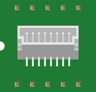
A Header 8 is a type of connector with 8 pins, typically used for connecting various electronic components or modules in a circuit. It allows for easy and secure connections, facilitating the integration of different parts in a system. Header 8 connectors are widely used in prototyping, PCB designs, and modular systems due to their simplicity and versatility.
Explore Projects Built with Header 8
 Open Project in Cirkit Designer
 Open Project in Cirkit Designer
 Open Project in Cirkit Designer
 Open Project in Cirkit Designer
Explore Projects Built with Header 8
Open Project in Cirkit DesignerOpen Project in Cirkit DesignerOpen Project in Cirkit DesignerOpen Project in Cirkit DesignerCommon Applications and Use Cases
- Connecting sensors, modules, or peripherals to microcontrollers.
- Establishing communication between PCBs in a multi-board system.
- Prototyping and breadboarding electronic circuits.
- Providing a reliable interface for detachable components.
Technical Specifications
Key Technical Details
- Number of Pins: 8
- Pin Spacing (Pitch): 2.54 mm (standard)
- Current Rating: Typically up to 3A per pin (varies by manufacturer)
- Voltage Rating: Typically up to 250V (varies by manufacturer)
- Material: Gold-plated or tin-plated copper pins, plastic housing
- Mounting Type: Through-hole or surface-mount
- Operating Temperature: -40°C to 105°C (varies by manufacturer)
Pin Configuration and Descriptions
The Header 8 connector consists of 8 pins arranged in a single row or dual row. The pin configuration is generic and depends on the application. Below is an example of a single-row Header 8 pinout:
| Pin Number | Description |
|---|---|
| 1 | Signal or Power (VCC) |
| 2 | Signal or Ground (GND) |
| 3 | Signal Line |
| 4 | Signal Line |
| 5 | Signal Line |
| 6 | Signal Line |
| 7 | Signal Line |
| 8 | Signal Line |
Note: The actual pin assignments depend on the circuit design and application.
Usage Instructions
How to Use the Component in a Circuit
Mounting the Header 8:
- For through-hole headers, insert the pins into the PCB holes and solder them securely.
- For surface-mount headers, align the pins with the PCB pads and solder them using reflow or manual soldering techniques.
Connecting Components:
- Use jumper wires, ribbon cables, or compatible connectors to establish connections with the Header 8.
- Ensure proper alignment of the pins to avoid incorrect connections.
Integration with Microcontrollers:
- Header 8 connectors are commonly used to interface with microcontrollers like Arduino UNO. For example, you can connect sensors or modules to the Arduino using a Header 8.
Important Considerations and Best Practices
- Pin Alignment: Double-check the pin alignment to avoid short circuits or incorrect connections.
- Current and Voltage Ratings: Ensure the current and voltage do not exceed the specified ratings to prevent damage.
- Soldering: Use proper soldering techniques to ensure reliable connections and avoid cold solder joints.
- Strain Relief: If the Header 8 is used with cables, consider adding strain relief to prevent mechanical stress on the pins.
Example: Connecting a Header 8 to an Arduino UNO
Below is an example of how to use a Header 8 to connect an LED module to an Arduino UNO:
// Example: Controlling an LED module connected via Header 8
// Pin 1: VCC (5V from Arduino)
// Pin 2: GND (Ground from Arduino)
// Pin 3: Signal (Connected to Arduino pin 9)

const int ledPin = 9; // Define the Arduino pin connected to the LED module

void setup() {
  pinMode(ledPin, OUTPUT); // Set the LED pin as an output
}

void loop() {
  digitalWrite(ledPin, HIGH); // Turn the LED on
  delay(1000);                // Wait for 1 second
  digitalWrite(ledPin, LOW);  // Turn the LED off
  delay(1000);                // Wait for 1 second
}
Note: Ensure the LED module is compatible with the Arduino's voltage and current output.
Troubleshooting and FAQs
Common Issues Users Might Face
Loose Connections:
- Problem: The connection between the Header 8 and the cable or component is loose.
- Solution: Ensure the connector is properly seated and consider using locking connectors if necessary.
Incorrect Pin Mapping:
- Problem: The pins are connected incorrectly, causing the circuit to malfunction.
- Solution: Double-check the pin mapping and ensure proper alignment with the circuit design.
Cold Solder Joints:
- Problem: Poor soldering results in unreliable connections.
- Solution: Re-solder the joints using proper soldering techniques and ensure the solder flows evenly.
Overcurrent or Overvoltage:
- Problem: The current or voltage exceeds the Header 8's rating, causing damage.
- Solution: Verify the current and voltage requirements of the circuit and ensure they are within the Header 8's specifications.
FAQs
Q: Can I use a Header 8 for high-frequency signals?
- A: Yes, but ensure the connector and PCB layout are designed to minimize signal interference and crosstalk.
Q: Are Header 8 connectors compatible with breadboards?
- A: Yes, Header 8 connectors with a 2.54 mm pitch are compatible with standard breadboards.
Q: Can I use a Header 8 for power connections?
- A: Yes, as long as the current and voltage do not exceed the connector's ratings.
Q: How do I clean a Header 8 connector?
- A: Use a soft brush or compressed air to remove dust. For stubborn dirt, use isopropyl alcohol and a lint-free cloth.
By following this documentation, you can effectively use a Header 8 connector in your electronic projects!