How to Use DC-AC Solid State Relay: Examples, Pinouts, and Specs
Introduction
A DC-AC Solid State Relay (SSR) is an electronic switching device designed to control AC loads using a DC control signal. Unlike traditional mechanical relays, SSRs use semiconductor components such as thyristors, triacs, or transistors to perform switching operations. This design eliminates moving parts, resulting in faster switching speeds, longer operational life, and silent operation.
Explore Projects Built with DC-AC Solid State Relay


Explore Projects Built with DC-AC Solid State Relay
Common Applications and Use Cases
- Industrial automation and process control
- Heating, ventilation, and air conditioning (HVAC) systems
- Motor control and lighting systems
- Home appliances and smart home devices
- Power distribution and load management
Technical Specifications
Key Technical Details
- Control Voltage (Input): Typically 3-32V DC
- Load Voltage (Output): 24-480V AC (varies by model)
- Load Current: 2A to 100A (depending on the relay rating)
- Switching Speed: Typically in the range of milliseconds
- Isolation Voltage: Up to 4000V between input and output
- Operating Temperature Range: -30°C to +80°C
- Dielectric Strength: 2500V AC (minimum)
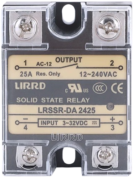
Pin Configuration and Descriptions
The DC-AC Solid State Relay typically has four terminals: two for the control input and two for the load output. Below is a table describing the pin configuration:
| Pin Number | Name | Description |
|---|---|---|
| 1 | DC+ (Input) | Positive terminal for the DC control signal. |
| 2 | DC- (Input) | Negative terminal for the DC control signal. |
| 3 | AC Load (L1) | Connects to one side of the AC load. |
| 4 | AC Load (L2) | Connects to the other side of the AC load. |
Note: Some SSRs may include additional features such as status LEDs or snubber circuits, which may slightly alter the pin configuration.
Usage Instructions
How to Use the Component in a Circuit
Connect the Control Signal:
- Attach the positive DC control signal to the DC+ terminal (Pin 1).
- Connect the ground of the control signal to the DC- terminal (Pin 2).
- Ensure the control voltage is within the specified range (e.g., 3-32V DC).
Connect the Load:
- Connect one terminal of the AC load to the AC Load (L1) terminal (Pin 3).
- Connect the other terminal of the AC load to the AC Load (L2) terminal (Pin 4).
- Ensure the load voltage and current are within the relay's rated specifications.
Power the Circuit:
- Apply the DC control signal to activate the relay. When the control signal is applied, the SSR will switch the AC load on.
- Remove the control signal to turn the AC load off.
Important Considerations and Best Practices
- Heat Dissipation: SSRs generate heat during operation. Use a heatsink or proper ventilation to prevent overheating, especially for high-current loads.
- Snubber Circuit: For inductive loads (e.g., motors), use a snubber circuit to suppress voltage spikes and protect the relay.
- Isolation: Ensure proper electrical isolation between the control and load sides to prevent damage to sensitive components.
- Polarity: Observe the correct polarity for the DC control signal to avoid malfunction or damage.
- Load Ratings: Do not exceed the relay's voltage and current ratings to ensure safe and reliable operation.
Example: Connecting to an Arduino UNO
Below is an example of how to control a DC-AC SSR using an Arduino UNO:
// Example: Controlling a DC-AC Solid State Relay with Arduino UNO
// This code turns an AC load on and off using a DC-AC SSR.

const int relayPin = 7; // Pin connected to the DC+ terminal of the SSR

void setup() {
  pinMode(relayPin, OUTPUT); // Set the relay pin as an output
}

void loop() {
  digitalWrite(relayPin, HIGH); // Turn the AC load ON
  delay(5000);                 // Keep the load ON for 5 seconds
  digitalWrite(relayPin, LOW); // Turn the AC load OFF
  delay(5000);                 // Keep the load OFF for 5 seconds
}
Note: Ensure the Arduino's ground (GND) is connected to the DC- terminal of the SSR.
Troubleshooting and FAQs
Common Issues and Solutions
Relay Not Switching:
- Cause: Insufficient control voltage or incorrect polarity.
- Solution: Verify the control voltage is within the specified range and check the polarity.
Excessive Heat:
- Cause: High load current or inadequate heat dissipation.
- Solution: Use a heatsink or improve ventilation around the relay.
Load Not Turning Off:
- Cause: Inductive load causing voltage spikes.
- Solution: Add a snubber circuit or RC network across the load terminals.
Flickering Load:
- Cause: Unstable control signal or insufficient current drive.
- Solution: Ensure the control signal is stable and capable of providing sufficient current.
FAQs
Q1: Can I use a DC-AC SSR to control a DC load?
A1: No, DC-AC SSRs are designed specifically for AC loads. For DC loads, use a DC-DC SSR.
Q2: Is it safe to use an SSR without a heatsink?
A2: For low-current applications, a heatsink may not be necessary. However, for high-current loads, a heatsink is essential to prevent overheating.
Q3: How do I know if the SSR is working?
A3: Many SSRs include an LED indicator that lights up when the control signal is applied. Additionally, you can measure the voltage across the load terminals to verify operation.
Q4: Can I use an SSR with a PWM signal?
A4: While SSRs can handle some PWM signals, their switching speed is limited. For high-frequency PWM, use a relay specifically designed for such applications.
By following this documentation, you can effectively integrate a DC-AC Solid State Relay into your projects and ensure reliable performance.