
How to Use ESP32-S3 N16R8: Examples, Pinouts, and Specs
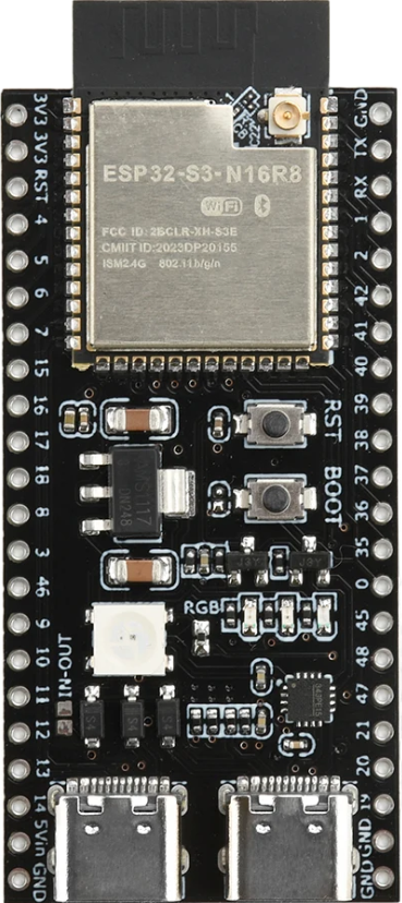
 Design with ESP32-S3 N16R8 in Cirkit Designer
Introduction
The ESP32-S3 N16R8, manufactured by Ali, is a powerful microcontroller designed for advanced IoT applications and complex processing tasks. It features integrated Wi-Fi and Bluetooth capabilities, making it an excellent choice for wireless communication projects. With 16MB of flash memory and 8MB of RAM, the ESP32-S3 N16R8 is well-suited for applications requiring high performance, such as machine learning, edge computing, and multimedia processing.
Explore Projects Built with ESP32-S3 N16R8
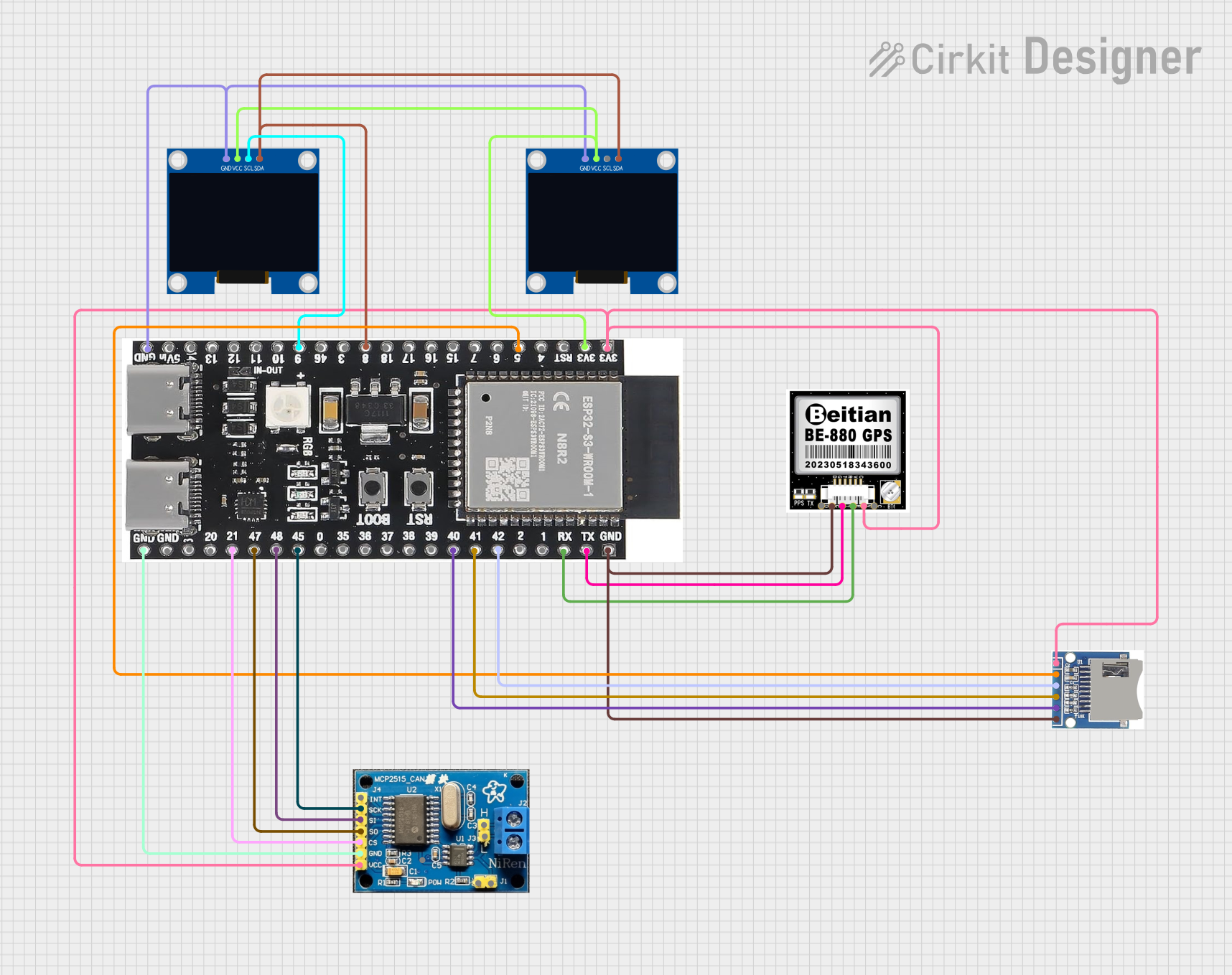 Open Project in Cirkit Designer
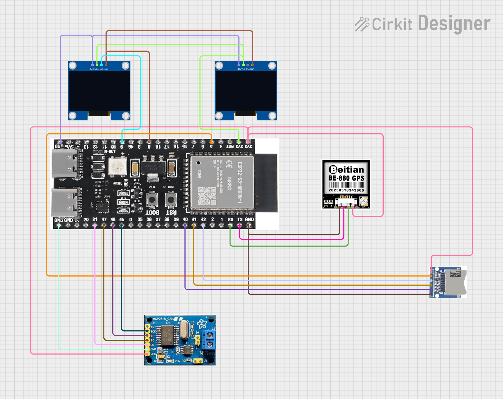 Open Project in Cirkit Designer
 Open Project in Cirkit Designer
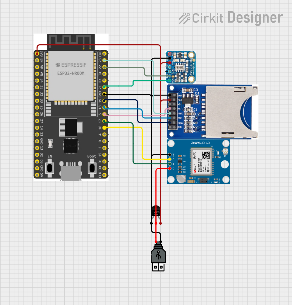 Open Project in Cirkit Designer
Explore Projects Built with ESP32-S3 N16R8
Open Project in Cirkit DesignerOpen Project in Cirkit DesignerOpen Project in Cirkit DesignerOpen Project in Cirkit DesignerCommon Applications and Use Cases
- IoT devices and smart home automation
- Wireless sensor networks
- Machine learning and AI at the edge
- Multimedia streaming and processing
- Industrial automation and robotics
- Wearable devices and health monitoring systems
Technical Specifications
The following table outlines the key technical specifications of the ESP32-S3 N16R8:
| Specification | Details |
|---|---|
| Manufacturer | Ali |
| Microcontroller | ESP32-S3 |
| Flash Memory | 16MB |
| RAM | 8MB |
| Wireless Connectivity | Wi-Fi 802.11 b/g/n, Bluetooth 5.0 (LE) |
| Operating Voltage | 3.0V to 3.6V |
| GPIO Pins | 45 |
| ADC Channels | 20 |
| DAC Channels | 2 |
| Communication Interfaces | UART, SPI, I2C, I2S, CAN, Ethernet |
| Clock Speed | Up to 240 MHz |
| Power Consumption | Ultra-low power modes available |
| Operating Temperature | -40°C to +85°C |
| Package Type | QFN48 |
Pin Configuration and Descriptions
The ESP32-S3 N16R8 has a total of 45 GPIO pins, which can be configured for various functions. Below is a table summarizing the key pins and their descriptions:
| Pin Name | Function | Description |
|---|---|---|
| GPIO0 | Input/Output, Boot Mode Select | Used for boot mode selection during startup. |
| GPIO1 | UART TX | Transmit pin for UART communication. |
| GPIO3 | UART RX | Receive pin for UART communication. |
| GPIO4 | Input/Output, ADC1_CH0 | General-purpose I/O or ADC channel 0. |
| GPIO5 | Input/Output, PWM | General-purpose I/O or PWM signal output. |
| GPIO18 | SPI CLK | Clock pin for SPI communication. |
| GPIO19 | SPI MISO | Master In Slave Out pin for SPI communication. |
| GPIO23 | SPI MOSI | Master Out Slave In pin for SPI communication. |
| GPIO25 | DAC1 | Digital-to-Analog Converter channel 1. |
| GPIO26 | DAC2 | Digital-to-Analog Converter channel 2. |
| GPIO36 | ADC1_CH0 | Analog-to-Digital Converter channel 0. |
| EN | Enable | Chip enable pin. Pull high to enable the chip. |
| 3V3 | Power Supply | 3.3V power input. |
| GND | Ground | Ground connection. |
Note: Many GPIO pins are multiplexed and can serve multiple functions. Refer to the ESP32-S3 datasheet for detailed pin mapping.
Usage Instructions
How to Use the ESP32-S3 N16R8 in a Circuit
- Power Supply: Provide a stable 3.3V power supply to the
3V3pin and connect theGNDpin to ground. - Boot Mode: To flash firmware, connect GPIO0 to ground during startup. After flashing, disconnect GPIO0 from ground.
- Programming: Use a USB-to-UART converter to connect the ESP32-S3 to your computer. Connect the UART TX and RX pins to the converter, and ensure the EN pin is pulled high.
- Peripherals: Connect sensors, actuators, or other peripherals to the GPIO pins. Configure the pins in your firmware as needed.
Important Considerations and Best Practices
- Voltage Levels: Ensure all connected peripherals operate at 3.3V logic levels to avoid damaging the ESP32-S3.
- Decoupling Capacitors: Place decoupling capacitors (e.g., 0.1µF) near the power pins to reduce noise and improve stability.
- Antenna Placement: For optimal Wi-Fi and Bluetooth performance, ensure the onboard antenna is not obstructed by metal or other conductive materials.
- Firmware Updates: Use the latest ESP-IDF (Espressif IoT Development Framework) for programming and updating the firmware.
Example Code for Arduino UNO Integration
The ESP32-S3 can be programmed using the Arduino IDE. Below is an example of how to connect the ESP32-S3 to a Wi-Fi network:
#include <WiFi.h> // Include the Wi-Fi library for ESP32

const char* ssid = "Your_SSID";       // Replace with your Wi-Fi network name
const char* password = "Your_Password"; // Replace with your Wi-Fi password

void setup() {
  Serial.begin(115200); // Initialize serial communication at 115200 baud
  WiFi.begin(ssid, password); // Start connecting to Wi-Fi

  Serial.print("Connecting to Wi-Fi");
  while (WiFi.status() != WL_CONNECTED) {
    delay(500); // Wait for connection
    Serial.print(".");
  }
  Serial.println("\nConnected to Wi-Fi!");
  Serial.print("IP Address: ");
  Serial.println(WiFi.localIP()); // Print the assigned IP address
}

void loop() {
  // Add your main code here
}
Note: Replace
Your_SSIDandYour_Passwordwith your Wi-Fi credentials.
Troubleshooting and FAQs
Common Issues and Solutions
ESP32-S3 Not Connecting to Wi-Fi
- Solution: Double-check the SSID and password. Ensure the Wi-Fi network is operational and within range.
- Tip: Use a serial monitor to debug connection issues.
GPIO Pins Not Responding
- Solution: Verify the pin configuration in your code. Ensure the pins are not being used for multiple conflicting functions.
- Tip: Use a multimeter to check for proper voltage levels on the pins.
Device Not Detected by Computer
- Solution: Ensure the USB-to-UART driver is installed on your computer. Check the USB cable and connections.
- Tip: Try a different USB port or cable.
Overheating
- Solution: Check for excessive current draw from connected peripherals. Ensure proper ventilation.
- Tip: Use a heat sink if necessary for high-performance applications.
FAQs
Q: Can the ESP32-S3 N16R8 operate on battery power?
- A: Yes, it can operate on battery power. Use a 3.3V regulator to ensure a stable voltage supply.
Q: How do I reset the ESP32-S3?
- A: Pull the EN pin low momentarily to reset the device.
Q: Can I use the ESP32-S3 for Bluetooth audio streaming?
- A: Yes, the ESP32-S3 supports Bluetooth 5.0 and can handle audio streaming applications.
Q: What development tools are recommended?
- A: Use the ESP-IDF or Arduino IDE for programming. Both provide extensive libraries and examples.
This concludes the documentation for the ESP32-S3 N16R8. For further details, refer to the official datasheet and user manual provided by Ali.