How to Use REF-14C: Examples, Pinouts, and Specs
Introduction
The REF-14C is a radial leaded resistor manufactured by RUET Electra Force. This passive electronic component is designed to offer resistance of 14Ω with a power rating of 1/4 watt and a tolerance of ±5%. Radial leaded resistors like the REF-14C are commonly used in various electronic circuits to limit current, divide voltages, and provide biasing for active elements.
Explore Projects Built with REF-14C


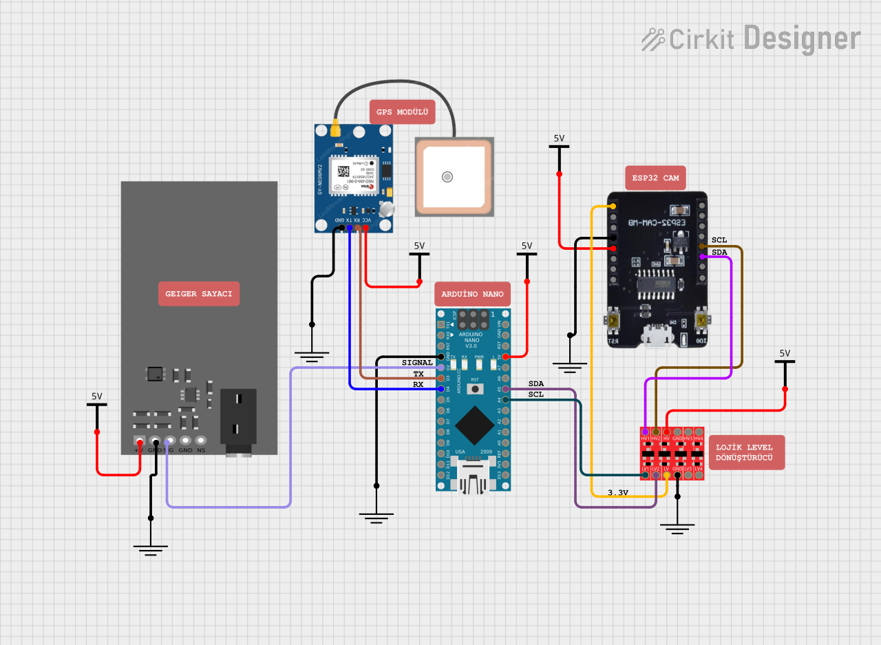
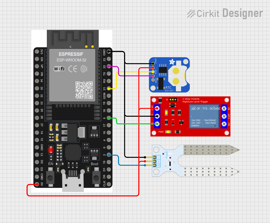
Explore Projects Built with REF-14C
Common Applications and Use Cases
- Voltage regulation in power supplies
- Current limiting for LEDs and other sensitive components
- Pull-up or pull-down resistors in digital circuits
- Impedance matching in audio and RF circuits
- Analog circuit filtering and timing with capacitors
Technical Specifications
Key Technical Details
- Resistance: 14Ω
- Tolerance: ±5%
- Power Rating: 1/4 watt (0.25W)
- Temperature Coefficient: Typically around ±200 ppm/°C
- Operating Temperature Range: -55°C to 155°C
Pin Configuration and Descriptions
| Pin | Description |
|---|---|
| 1 | Lead connected to one end of the resistive material |
| 2 | Lead connected to the other end of the resistive material |
Usage Instructions
How to Use the Component in a Circuit
- Identify the Leads: Locate the two leads of the REF-14C resistor.
- Orientation: The REF-14C resistor is non-polarized, meaning it can be connected in any direction.
- Soldering: Solder the leads into the designated places on the PCB or use a breadboard for prototyping.
- Current Calculation: Ensure the current through the resistor does not exceed the power rating using the formula
I = sqrt(P/R)whereIis the current,Pis the power rating, andRis the resistance.
Important Considerations and Best Practices
- Power Dissipation: Do not exceed the 1/4 watt power rating to prevent damage.
- Tolerance: Account for the ±5% tolerance when designing circuits that require precise resistance values.
- Thermal Management: Provide adequate spacing around the resistor to allow for heat dissipation.
- Soldering: Avoid prolonged heat exposure during soldering to prevent damage to the resistor.
Troubleshooting and FAQs
Common Issues
- Excessive Heat: If the resistor is too hot, check if the power rating has been exceeded.
- Open Circuit: A lack of continuity could indicate a damaged resistor.
- Unexpected Resistance Value: Ensure the resistor is not within the tolerance range or affected by nearby components.
Solutions and Tips for Troubleshooting
- Power Exceedance: Recalculate the current and voltage to ensure they are within the specified limits.
- Continuity Check: Use a multimeter to check for continuity. Replace the resistor if it's damaged.
- Resistance Measurement: Measure the resistance with a multimeter to confirm it's within the expected range considering the tolerance.
FAQs
Q: Can I use the REF-14C in a high-frequency circuit? A: Yes, but be aware that parasitic inductance and capacitance may affect performance at very high frequencies.
Q: What happens if I exceed the power rating? A: Exceeding the power rating can lead to resistor failure, potentially damaging the circuit.
Q: Is the REF-14C suitable for automotive applications? A: It depends on the specific conditions. The operating temperature range should be considered, and the component should meet any additional automotive standards.
Example Arduino UNO Connection
// Connect one lead of the REF-14C to Arduino pin 13 and the other lead to GND.

void setup() {
  pinMode(13, OUTPUT); // Set pin 13 as an output
}

void loop() {
  digitalWrite(13, HIGH); // Apply voltage across the resistor
  delay(1000);            // Wait for 1 second
  digitalWrite(13, LOW);  // Remove the voltage
  delay(1000);            // Wait for 1 second
}
Note: The above example assumes that the current through the REF-14C does not exceed its power rating when connected to the Arduino pin. Always calculate the expected current and confirm it is within safe limits.