Cirkit Designer Logo
Cirkit Designer
Your all-in-one circuit design IDE
Home / 
Component Documentation

How to Use NFC/RFID reader: Examples, Pinouts, and Specs

Image of NFC/RFID reader
Cirkit Designer LogoDesign with NFC/RFID reader in Cirkit Designer

Introduction

The NFC/RFID Reader PN532 v.3 is a versatile and user-friendly module that enables wireless communication using Near Field Communication (NFC) or Radio-Frequency Identification (RFID) technologies. This reader is capable of reading and writing to NFC and RFID tags operating at the 13.56 MHz frequency. It is commonly used in applications such as contactless payment systems, access control, and data exchange between devices.

Explore Projects Built with NFC/RFID reader

Use Cirkit Designer to design, explore, and prototype these projects online. Some projects support real-time simulation. Click "Open Project" to start designing instantly!
Arduino UNO Based NFC Reader with Membrane Keypad Interface
Image of NFC_serial: A project utilizing NFC/RFID reader in a practical application
This circuit features an Arduino UNO connected to a 4x4 membrane matrix keypad, an NFC/RFID reader, and powered by a 9V battery. The Arduino is programmed to detect and display keypad inputs and read NFC tags, likely for an access control or identification system. The NFC/RFID reader communicates with the Arduino via I2C (using SDA and SCL lines), and the keypad is interfaced using digital IO pins.
Cirkit Designer LogoOpen Project in Cirkit Designer
Biometric Access Control System with RFID and Touch Activation
Image of DOORLOCK1: A project utilizing NFC/RFID reader in a practical application
This circuit is designed for security and identification purposes, featuring an RFID-RC522 module for contactless communication and a fingerprint scanner for biometric authentication. It includes an LCD display for user interaction, a touch sensor for input, a buzzer for audio feedback, and a relay module for controlling external devices. The components are interfaced with a NANO Expansion board, which likely contains a microcontroller to coordinate the operations of the system.
Cirkit Designer LogoOpen Project in Cirkit Designer
Arduino Mega and UNO-Based NFC/RFID Reader with SD Card Data Logging
Image of nfc: A project utilizing NFC/RFID reader in a practical application
This circuit integrates an Arduino Mega 2560 and an Arduino UNO to interface with an SD card module and an NFC/RFID reader. The Arduino Mega 2560 reads analog values from various MQ sensors and logs data to the SD card, while the Arduino UNO handles communication with the NFC/RFID reader.
Cirkit Designer LogoOpen Project in Cirkit Designer
Arduino UNO Based RFID Access Control with 433MHz RF Communication
Image of Interior of main: A project utilizing NFC/RFID reader in a practical application
This circuit is designed to read RFID tags, display information on an LCD, and communicate wirelessly using 433MHz RF modules. It is controlled by an Arduino UNO, which processes inputs from multiple pushbuttons and manages the RFID reader and RF communication.
Cirkit Designer LogoOpen Project in Cirkit Designer

Explore Projects Built with NFC/RFID reader

Use Cirkit Designer to design, explore, and prototype these projects online. Some projects support real-time simulation. Click "Open Project" to start designing instantly!
Image of NFC_serial: A project utilizing NFC/RFID reader in a practical application
Arduino UNO Based NFC Reader with Membrane Keypad Interface
This circuit features an Arduino UNO connected to a 4x4 membrane matrix keypad, an NFC/RFID reader, and powered by a 9V battery. The Arduino is programmed to detect and display keypad inputs and read NFC tags, likely for an access control or identification system. The NFC/RFID reader communicates with the Arduino via I2C (using SDA and SCL lines), and the keypad is interfaced using digital IO pins.
Cirkit Designer LogoOpen Project in Cirkit Designer
Image of DOORLOCK1: A project utilizing NFC/RFID reader in a practical application
Biometric Access Control System with RFID and Touch Activation
This circuit is designed for security and identification purposes, featuring an RFID-RC522 module for contactless communication and a fingerprint scanner for biometric authentication. It includes an LCD display for user interaction, a touch sensor for input, a buzzer for audio feedback, and a relay module for controlling external devices. The components are interfaced with a NANO Expansion board, which likely contains a microcontroller to coordinate the operations of the system.
Cirkit Designer LogoOpen Project in Cirkit Designer
Image of nfc: A project utilizing NFC/RFID reader in a practical application
Arduino Mega and UNO-Based NFC/RFID Reader with SD Card Data Logging
This circuit integrates an Arduino Mega 2560 and an Arduino UNO to interface with an SD card module and an NFC/RFID reader. The Arduino Mega 2560 reads analog values from various MQ sensors and logs data to the SD card, while the Arduino UNO handles communication with the NFC/RFID reader.
Cirkit Designer LogoOpen Project in Cirkit Designer
Image of Interior of main: A project utilizing NFC/RFID reader in a practical application
Arduino UNO Based RFID Access Control with 433MHz RF Communication
This circuit is designed to read RFID tags, display information on an LCD, and communicate wirelessly using 433MHz RF modules. It is controlled by an Arduino UNO, which processes inputs from multiple pushbuttons and manages the RFID reader and RF communication.
Cirkit Designer LogoOpen Project in Cirkit Designer

Technical Specifications

Key Technical Details

  • Operating Voltage: 3.3V to 5.5V
  • Operating Current (typical): 100mA
  • Frequency: 13.56MHz
  • Supported Protocols: ISO/IEC 14443 A and B, FeliCa, and NFC Forum tags
  • Interface: I2C, SPI, and HSU (High-Speed UART)
  • Reading Distance: Up to 7 cm (depending on the tag type)
  • Dimensions: 43 x 40 mm

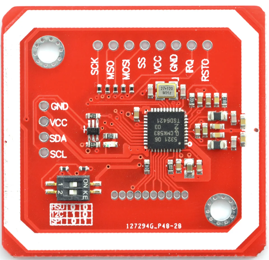
Pin Configuration and Descriptions

Pin Number Name Description
1 VCC Power supply (3.3V to 5.5V)
2 GND Ground
3 SDA I2C Data / SPI Serial Data In (MOSI)
4 SCL I2C Clock / SPI Serial Clock
5 MISO SPI Serial Data Out
6 IRQ Interrupt request (active low)
7 RSTO Reset output (active low)
8 SSEL SPI Slave Select

Usage Instructions

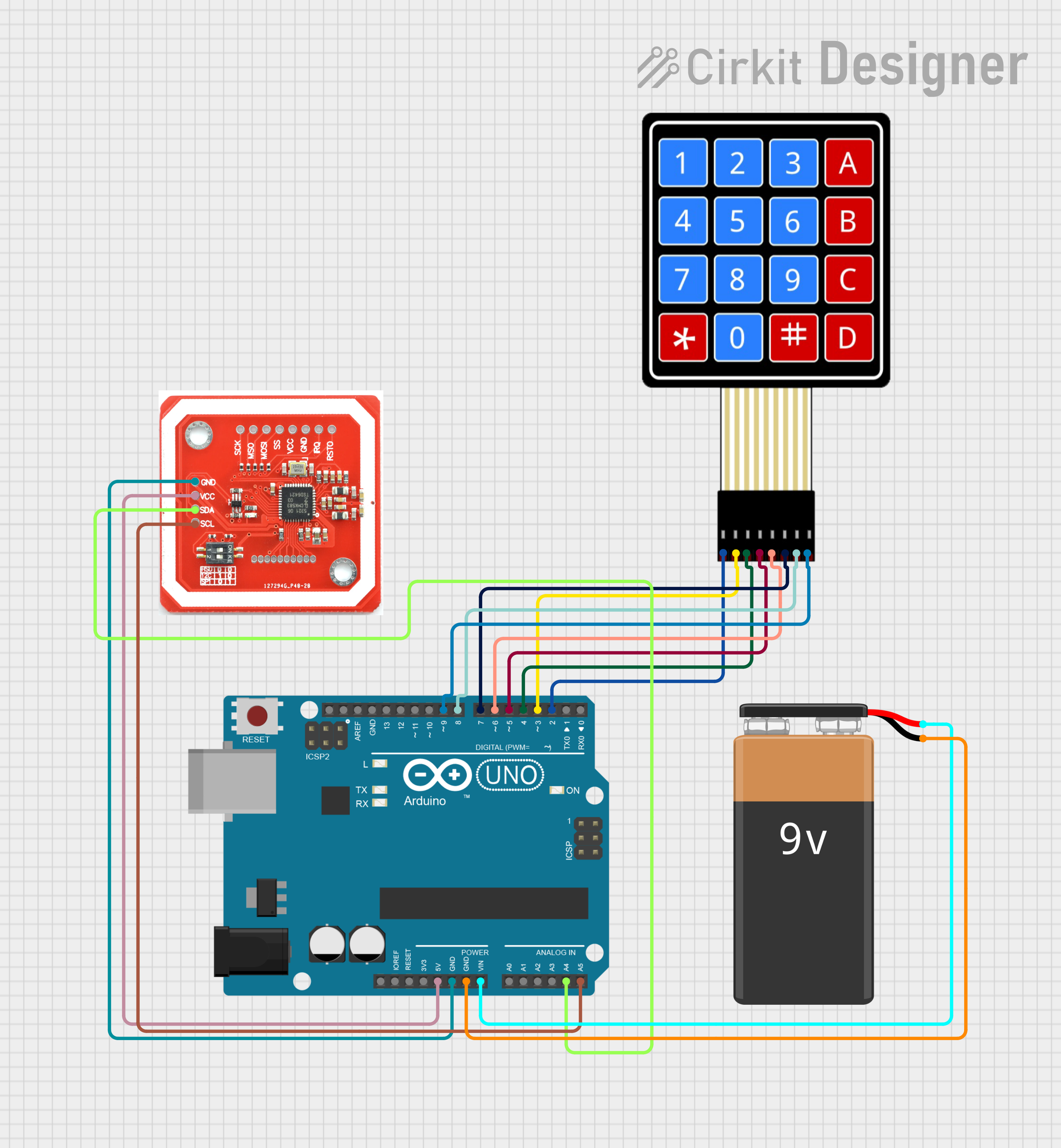
Connecting to an Arduino UNO

  1. Power Connections:

    • Connect the VCC pin to the 5V output on the Arduino.
    • Connect the GND pin to a ground pin on the Arduino.
  2. Data Connections (I2C):

    • Connect the SDA pin to the A4 pin (SDA) on the Arduino.
    • Connect the SCL pin to the A5 pin (SCL) on the Arduino.
  3. Data Connections (SPI):

    • Connect the SDA (MOSI) pin to the D11 pin on the Arduino.
    • Connect the SCL (SCK) pin to the D13 pin on the Arduino.
    • Connect the MISO pin to the D12 pin on the Arduino.
    • Connect the SSEL pin to the D10 pin on the Arduino.

Programming the Arduino

To use the PN532 NFC/RFID reader with an Arduino, you will need to use a library such as the "Adafruit_PN532" library which can be installed via the Arduino Library Manager.

#include <Wire.h>
#include <Adafruit_PN532.h>

// If using the I2C interface
Adafruit_PN532 nfc(PN532_SDA, PN532_SCL);

void setup(void) {
  Serial.begin(115200);
  Serial.println("Hello! Scan your NFC tag!");

  nfc.begin();
  uint32_t versiondata = nfc.getFirmwareVersion();
  if (!versiondata) {
    Serial.print("Didn't find PN53x board");
    while (1); // halt
  }
  // Configure board to read RFID tags
  nfc.SAMConfig();
}

void loop(void) {
  uint8_t success;
  uint8_t uid[] = { 0, 0, 0, 0, 0, 0, 0 }; // Buffer to store the returned UID
  uint8_t uidLength; // Length of the UID (4 or 7 bytes depending on ISO14443A card type)

  // Wait for an ISO14443A type cards (Mifare, etc.). When one is found
  // 'uid' will be populated with the UID, and uidLength will indicate
  // if it's a 4-byte or 7-byte UID
  success = nfc.readPassiveTargetID(PN532_MIFARE_ISO14443A, uid, &uidLength);

  if (success) {
    Serial.println("Found an NFC tag!");
    Serial.print("UID Length: ");Serial.print(uidLength, DEC);Serial.println(" bytes");
    Serial.print("UID Value: ");
    for (uint8_t i=0; i < uidLength; i++) {
      Serial.print(" 0x");Serial.print(uid[i], HEX);
    }
    Serial.println("");
    // Wait 1 second before continuing
    delay(1000);
  }
}

Important Considerations and Best Practices

  • Ensure that the power supply is within the specified range (3.3V to 5.5V).
  • Use pull-up resistors if necessary when using the I2C interface.
  • Keep the reader away from metal surfaces to avoid interference with the RF field.
  • Place the NFC/RFID tag close to the reader for optimal reading distance.

Troubleshooting and FAQs

Common Issues

  • Reader not detecting tags: Ensure that the reader is correctly powered and that the tags are compatible and not damaged.
  • Communication errors: Check the wiring and connections, and ensure that the correct interface (I2C/SPI) is selected in your code.
  • Inconsistent reads: Make sure the tag is within the optimal reading distance and is not moving too quickly.

Solutions and Tips

  • Double-check the wiring against the pin configuration table.
  • Use the example code as a starting point and ensure the library is correctly installed.
  • If using SPI, ensure that other SPI devices are not interfering with the communication.

FAQs

Q: Can the PN532 v.3 read all types of NFC/RFID tags? A: The PN532 v.3 can read tags that operate at 13.56 MHz and support ISO/IEC 14443 A and B, FeliCa, and NFC Forum tags.

Q: How can I increase the reading distance? A: The reading distance is primarily determined by the antenna design and the tag itself. Using tags with larger antennas and ensuring minimal interference can help increase the reading distance.

Q: Is the PN532 v.3 compatible with all Arduino boards? A: The PN532 v.3 can be used with any Arduino board that supports I2C or SPI communication, provided the voltage levels are compatible.

For further assistance, consult the manufacturer's datasheet and the community forums dedicated to Arduino and NFC/RFID technology.