Cirkit Designer Logo
Cirkit Designer
Your all-in-one circuit design IDE
Home / 
Component Documentation

How to Use ESP-01 Module: Examples, Pinouts, and Specs

Image of ESP-01 Module
Cirkit Designer LogoDesign with ESP-01 Module in Cirkit Designer

Introduction

The ESP-01 Module is a compact Wi-Fi microcontroller module based on the ESP8266 chip. It is widely used in Internet of Things (IoT) applications due to its built-in Wi-Fi capabilities, low cost, and ease of use. The module allows devices to connect to the internet or communicate with other devices wirelessly. It can be programmed using the Arduino IDE or other development environments, making it a versatile choice for hobbyists and professionals alike.

Explore Projects Built with ESP-01 Module

Use Cirkit Designer to design, explore, and prototype these projects online. Some projects support real-time simulation. Click "Open Project" to start designing instantly!
ESP-01 Based IR Remote Control Receiver
Image of Stock: A project utilizing ESP-01 Module in a practical application
This circuit consists of an ESP-01 microcontroller connected to an IR receiver. The ESP-01 is configured to receive data from the IR receiver through its GPIO0 pin, and both components share a common ground and power connection. The provided code for the ESP-01 microcontroller is a template with empty setup and loop functions, indicating that the specific functionality for the IR data processing has not been implemented yet.
Cirkit Designer LogoOpen Project in Cirkit Designer
ESP8266 WiFi Module Serial Interface with Pushbutton Control
Image of esp01 progrmmer: A project utilizing ESP-01 Module in a practical application
This circuit features an ESP8266 ESP-01 WiFi module interfaced with an Adafruit FTDI Friend for serial communication. The ESP8266's TXD and RXD pins are connected to the FTDI's RX and TX pins respectively, allowing for data exchange between the microcontroller and a computer. Additionally, a pushbutton is connected to the ESP8266's reset pin, enabling manual resets of the module.
Cirkit Designer LogoOpen Project in Cirkit Designer
ESP32-Based Multi-Sensor Health Monitoring System with Bluetooth Connectivity
Image of circuit diagram: A project utilizing ESP-01 Module in a practical application
This circuit features an ESP32-WROOM-32UE microcontroller as the central processing unit, interfacing with a variety of sensors and modules. It includes a MAX30100 pulse oximeter and heart-rate sensor, an MLX90614 infrared thermometer, an HC-05 Bluetooth module for wireless communication, and a Neo 6M GPS module for location tracking. All components are powered by a common voltage supply and are connected to specific GPIO pins on the ESP32 for data exchange, with the sensors using I2C communication and the modules using UART.
Cirkit Designer LogoOpen Project in Cirkit Designer
ESP8266 NodeMCU with GPS and LoRa Connectivity
Image of Copy of lora based gps traking: A project utilizing ESP-01 Module in a practical application
This circuit comprises an ESP8266 NodeMCU microcontroller interfaced with a LoRa Ra-02 SX1278 module for long-range communication and a GPS NEO 6M module for location tracking. The ESP8266 reads GPS data via UART and transmits it using the LoRa module, which is connected via SPI. A 3.7v battery powers the system, making it suitable for remote tracking applications.
Cirkit Designer LogoOpen Project in Cirkit Designer

Explore Projects Built with ESP-01 Module

Use Cirkit Designer to design, explore, and prototype these projects online. Some projects support real-time simulation. Click "Open Project" to start designing instantly!
Image of Stock: A project utilizing ESP-01 Module in a practical application
ESP-01 Based IR Remote Control Receiver
This circuit consists of an ESP-01 microcontroller connected to an IR receiver. The ESP-01 is configured to receive data from the IR receiver through its GPIO0 pin, and both components share a common ground and power connection. The provided code for the ESP-01 microcontroller is a template with empty setup and loop functions, indicating that the specific functionality for the IR data processing has not been implemented yet.
Cirkit Designer LogoOpen Project in Cirkit Designer
Image of esp01 progrmmer: A project utilizing ESP-01 Module in a practical application
ESP8266 WiFi Module Serial Interface with Pushbutton Control
This circuit features an ESP8266 ESP-01 WiFi module interfaced with an Adafruit FTDI Friend for serial communication. The ESP8266's TXD and RXD pins are connected to the FTDI's RX and TX pins respectively, allowing for data exchange between the microcontroller and a computer. Additionally, a pushbutton is connected to the ESP8266's reset pin, enabling manual resets of the module.
Cirkit Designer LogoOpen Project in Cirkit Designer
Image of circuit diagram: A project utilizing ESP-01 Module in a practical application
ESP32-Based Multi-Sensor Health Monitoring System with Bluetooth Connectivity
This circuit features an ESP32-WROOM-32UE microcontroller as the central processing unit, interfacing with a variety of sensors and modules. It includes a MAX30100 pulse oximeter and heart-rate sensor, an MLX90614 infrared thermometer, an HC-05 Bluetooth module for wireless communication, and a Neo 6M GPS module for location tracking. All components are powered by a common voltage supply and are connected to specific GPIO pins on the ESP32 for data exchange, with the sensors using I2C communication and the modules using UART.
Cirkit Designer LogoOpen Project in Cirkit Designer
Image of Copy of lora based gps traking: A project utilizing ESP-01 Module in a practical application
ESP8266 NodeMCU with GPS and LoRa Connectivity
This circuit comprises an ESP8266 NodeMCU microcontroller interfaced with a LoRa Ra-02 SX1278 module for long-range communication and a GPS NEO 6M module for location tracking. The ESP8266 reads GPS data via UART and transmits it using the LoRa module, which is connected via SPI. A 3.7v battery powers the system, making it suitable for remote tracking applications.
Cirkit Designer LogoOpen Project in Cirkit Designer

Common Applications and Use Cases

  • Home automation systems
  • Wireless sensor networks
  • Smart appliances
  • Remote data logging
  • IoT prototyping and development
  • Wireless control of devices (e.g., relays, LEDs, motors)

Technical Specifications

Key Technical Details

  • Chipset: ESP8266
  • Operating Voltage: 3.0V to 3.6V (3.3V recommended)
  • Current Consumption:
    • Idle: ~70mA
    • Peak (Wi-Fi transmission): ~200mA
  • Wi-Fi Standards: 802.11 b/g/n
  • Flash Memory: 1MB (8Mbit)
  • GPIO Pins: 2 (GPIO0 and GPIO2)
  • Communication Protocols: UART, SPI, I2C (limited support)
  • Baud Rate: Default 115200 (configurable)
  • Dimensions: 14.3mm x 24.8mm

Pin Configuration and Descriptions

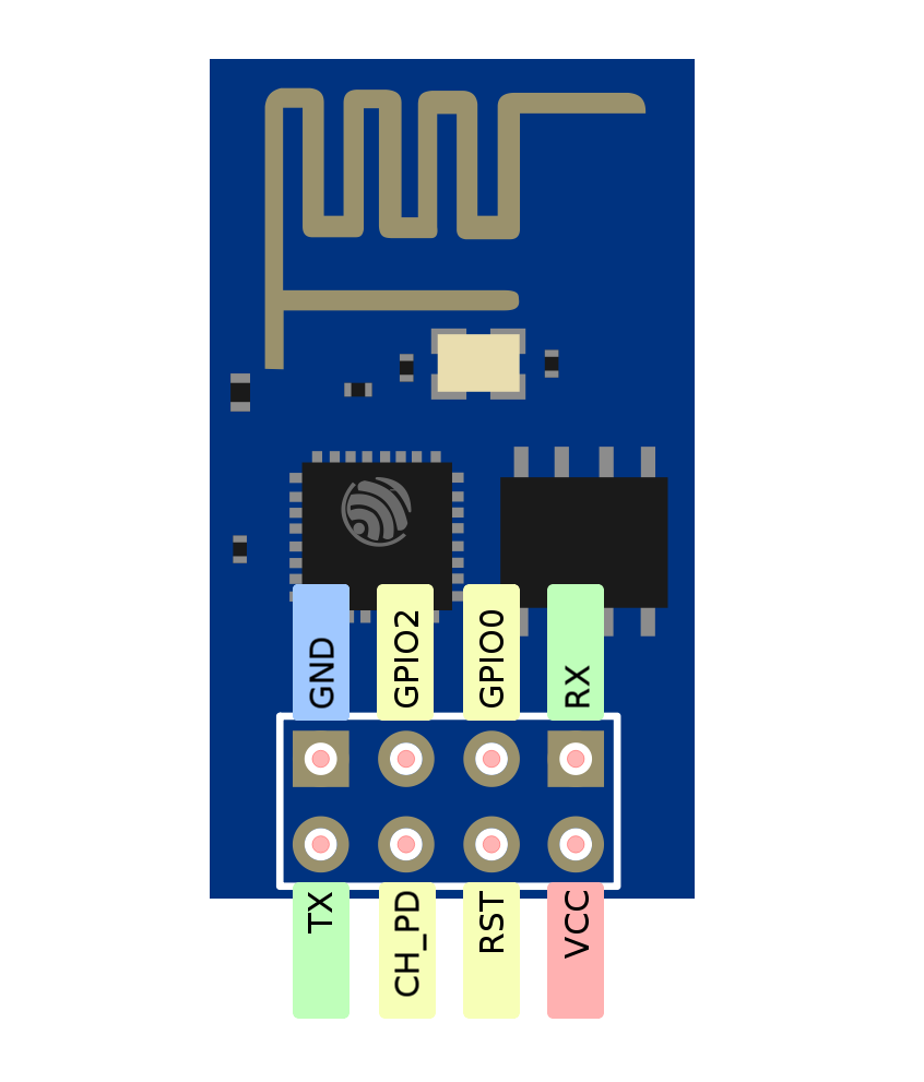
The ESP-01 Module has 8 pins, as shown below:

Pin Number Pin Name Description
1 GND Ground (0V reference)
2 GPIO2 General Purpose Input/Output Pin 2
3 GPIO0 General Purpose Input/Output Pin 0 (used for boot mode selection)
4 RX UART Receive Pin (used for serial communication)
5 TX UART Transmit Pin (used for serial communication)
6 CH_PD Chip Enable (must be pulled HIGH for normal operation)
7 VCC Power Supply (3.3V input)
8 RST Reset Pin (active LOW, used to reset the module)

Usage Instructions

How to Use the ESP-01 Module in a Circuit

  1. Power Supply: Ensure the module is powered with a stable 3.3V supply. Do not connect it directly to 5V as it may damage the module.
  2. Connections:
    • Connect the GND pin to the ground of your circuit.
    • Connect the VCC pin to a 3.3V power source.
    • Pull the CH_PD pin HIGH (connect it to 3.3V) to enable the module.
    • Use the RX and TX pins for serial communication with a microcontroller or USB-to-TTL adapter.
  3. Programming:
    • To upload code, connect GPIO0 to GND to enter programming mode.
    • After uploading, disconnect GPIO0 from GND and reset the module.

Important Considerations and Best Practices

  • Use a voltage regulator or level shifter if interfacing with 5V logic devices.
  • Add a 10µF capacitor between VCC and GND to stabilize the power supply.
  • Avoid excessive current draw on GPIO pins (maximum 12mA per pin).
  • Use a USB-to-TTL adapter with 3.3V logic levels for programming and communication.

Example: Connecting ESP-01 to Arduino UNO

Below is an example of using the ESP-01 Module with an Arduino UNO to connect to a Wi-Fi network and send data to a server.

Circuit Connections

  • ESP-01 VCC → 3.3V (external power supply)
  • ESP-01 GND → GND
  • ESP-01 RX → Arduino Pin 2 (via voltage divider for 3.3V logic)
  • ESP-01 TX → Arduino Pin 3
  • ESP-01 CH_PD → 3.3V
  • ESP-01 GPIO0 → Leave unconnected (HIGH by default)

Arduino Code

#include <SoftwareSerial.h>

// Define RX and TX pins for SoftwareSerial
SoftwareSerial espSerial(2, 3); // RX = Pin 2, TX = Pin 3

void setup() {
  // Start serial communication with ESP-01
  espSerial.begin(115200); 
  Serial.begin(9600); // For debugging via Serial Monitor

  // Send AT command to test communication
  Serial.println("Sending AT command...");
  espSerial.println("AT");
}

void loop() {
  // Check if ESP-01 has sent any data
  if (espSerial.available()) {
    String response = espSerial.readString();
    Serial.println("ESP-01 Response: " + response);
  }

  // Check if user has sent data via Serial Monitor
  if (Serial.available()) {
    String command = Serial.readString();
    espSerial.println(command); // Forward command to ESP-01
  }
}

Notes

  • Ensure the ESP-01 baud rate matches the espSerial.begin() value.
  • Use a level shifter or voltage divider for the Arduino TX pin to avoid damaging the ESP-01.

Troubleshooting and FAQs

Common Issues and Solutions

  1. ESP-01 Not Responding to AT Commands:

    • Ensure the module is powered with a stable 3.3V supply.
    • Verify the baud rate of the ESP-01 matches the serial communication settings.
    • Check the connections, especially RX and TX pins.
  2. Wi-Fi Connection Fails:

    • Double-check the SSID and password in your code.
    • Ensure the Wi-Fi network is within range and supports 2.4GHz (ESP-01 does not support 5GHz).
  3. Module Overheating:

    • Avoid powering the module directly from a 5V source.
    • Use a proper heat sink or ensure adequate ventilation.
  4. Upload Errors During Programming:

    • Ensure GPIO0 is connected to GND during programming.
    • Reset the module after uploading the code.

FAQs

  • Can the ESP-01 be used as a standalone microcontroller? Yes, the ESP-01 can be programmed using the Arduino IDE or other environments to function as a standalone microcontroller.

  • What is the maximum range of the ESP-01? The range depends on the environment but typically extends up to 100 meters in open spaces.

  • Can the ESP-01 operate on 5V? No, the ESP-01 operates on 3.3V. Using 5V can damage the module.

  • How do I restore the ESP-01 to factory settings? Send the AT+RESTORE command via serial communication to reset the module to its default state.