How to Use CURRENT SENSOR: Examples, Pinouts, and Specs
Introduction
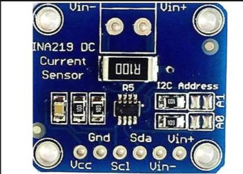
The 1NA219 Current Sensor by Texas Instruments (TI) is a precision device designed to measure the flow of electric current in a circuit. It provides an output signal proportional to the current level, enabling accurate monitoring and control of electrical systems. This sensor is widely used in applications requiring current measurement, such as battery management systems, power supplies, motor control, and energy monitoring.
Explore Projects Built with CURRENT SENSOR


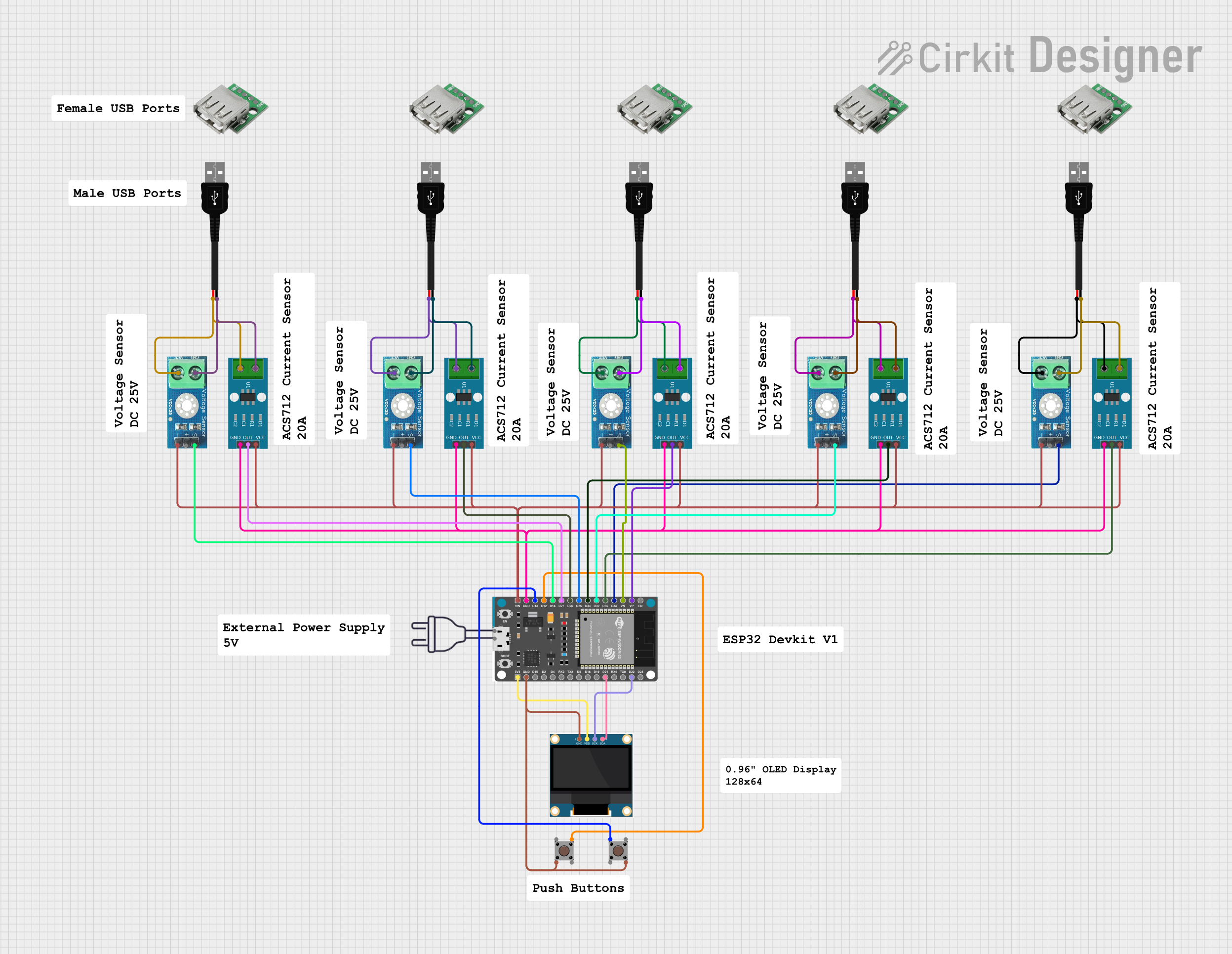
Explore Projects Built with CURRENT SENSOR
Common Applications:
- Battery charge and discharge monitoring
- Power supply efficiency analysis
- Motor current sensing
- Energy consumption tracking in IoT devices
- Overcurrent protection in circuits
Technical Specifications
The 1NA219 Current Sensor is a high-accuracy, bidirectional current sensing device with integrated features for ease of use. Below are its key technical details:
Key Specifications:
| Parameter | Value |
|---|---|
| Supply Voltage (Vcc) | 3.0V to 5.5V |
| Operating Current | 800 µA (typical) |
| Input Voltage Range | 0V to 26V |
| Current Measurement Range | ±3.2A (with default shunt) |
| Output Signal | I²C digital output |
| Accuracy | ±1% |
| Communication Protocol | I²C (7-bit address) |
| Operating Temperature | -40°C to +125°C |
Pin Configuration:
The 1NA219 comes in an 8-pin package. Below is the pinout and description:
| Pin Number | Pin Name | Description |
|---|---|---|
| 1 | VCC | Power supply input (3.0V to 5.5V) |
| 2 | GND | Ground connection |
| 3 | SDA | I²C data line |
| 4 | SCL | I²C clock line |
| 5 | A0 | I²C address selection bit 0 |
| 6 | A1 | I²C address selection bit 1 |
| 7 | VIN+ | Positive input for current sensing |
| 8 | VIN- | Negative input for current sensing |
Usage Instructions
How to Use the 1NA219 in a Circuit:
- Power Supply: Connect the VCC pin to a 3.3V or 5V power source and the GND pin to the ground.
- Current Sensing: Connect the VIN+ and VIN- pins across the shunt resistor or the load where current needs to be measured.
- I²C Communication: Connect the SDA and SCL pins to the corresponding I²C pins on your microcontroller (e.g., Arduino UNO).
- Address Configuration: Use the A0 and A1 pins to set the I²C address if multiple sensors are used on the same bus.
Important Considerations:
- Ensure the input voltage on VIN+ and VIN- does not exceed 26V.
- Use a suitable shunt resistor to match the current range of your application.
- Pull-up resistors (typically 4.7kΩ) are required on the SDA and SCL lines for proper I²C communication.
- Avoid placing the sensor near high-frequency noise sources to maintain accuracy.
Example Code for Arduino UNO:
Below is an example of how to interface the 1NA219 with an Arduino UNO to measure current:
#include <Wire.h>
#include <Adafruit_INA219.h>

// Create an instance of the INA219 sensor
Adafruit_INA219 ina219;

void setup() {
  Serial.begin(9600); // Initialize serial communication at 9600 baud
  while (!Serial) {
    // Wait for the serial port to connect (for native USB boards)
  }

  if (!ina219.begin()) {
    Serial.println("Failed to find INA219 chip");
    while (1) {
      delay(10); // Stay in loop if sensor initialization fails
    }
  }
  Serial.println("INA219 Current Sensor Initialized");
}

void loop() {
  float current_mA = 0.0;

  // Read current in milliamps
  current_mA = ina219.getCurrent_mA();

  // Print the current value to the Serial Monitor
  Serial.print("Current: ");
  Serial.print(current_mA);
  Serial.println(" mA");

  delay(1000); // Wait for 1 second before the next reading
}
Notes:
- Install the Adafruit_INA219 library in the Arduino IDE before running the code.
- Adjust the delay in the
loop()function as needed for your application.
Troubleshooting and FAQs
Common Issues:
No Output or Incorrect Readings:
- Ensure the VCC and GND pins are properly connected.
- Verify the I²C address matches the configuration of the A0 and A1 pins.
- Check for proper pull-up resistors on the SDA and SCL lines.
I²C Communication Failure:
- Confirm the I²C pins on the microcontroller are correctly connected to the sensor.
- Use an I²C scanner sketch to detect the sensor's address.
Overheating:
- Ensure the current through the shunt resistor does not exceed its rated capacity.
- Verify the input voltage on VIN+ and VIN- is within the specified range.
FAQs:
Q1: Can the 1NA219 measure negative currents?
Yes, the sensor supports bidirectional current measurement. Ensure the shunt resistor is correctly placed to measure current in both directions.
Q2: What is the maximum current the 1NA219 can measure?
The maximum measurable current depends on the value of the shunt resistor. With the default 0.1Ω shunt, the range is ±3.2A.
Q3: Can I use the 1NA219 with a 3.3V microcontroller?
Yes, the sensor operates with a supply voltage of 3.0V to 5.5V, making it compatible with both 3.3V and 5V systems.
Q4: How do I increase the measurement range?
To increase the range, use a smaller shunt resistor. However, this may reduce measurement resolution.
By following this documentation, users can effectively integrate the 1NA219 Current Sensor into their projects for precise current measurement and monitoring.