Cirkit Designer
Your all-in-one circuit design IDE
Home /
Component Documentation
How to Use esp8266 custom board: Examples, Pinouts, and Specs
Introduction
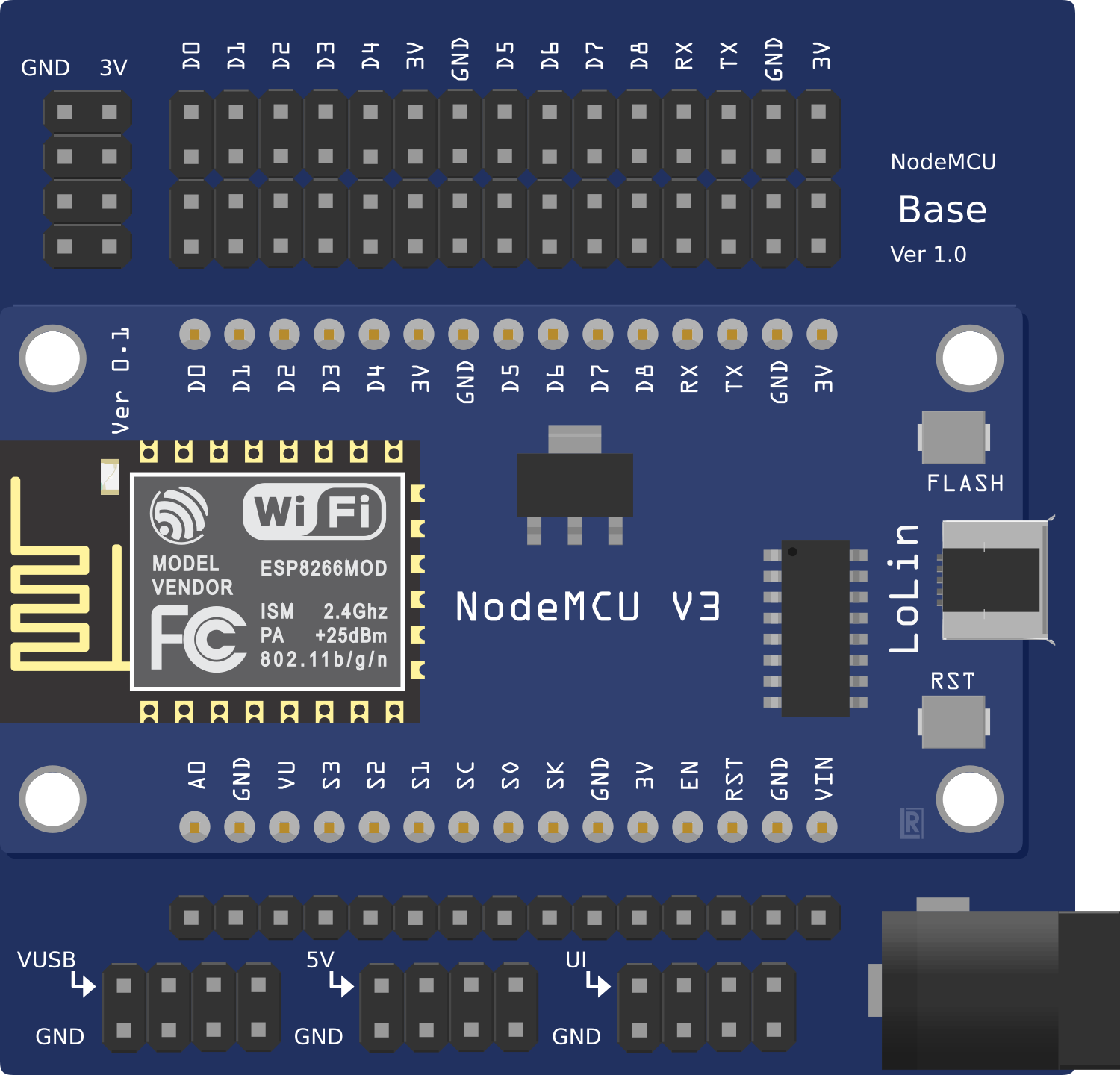
The ESP8266 Custom Board is a development board based on the ESP8266 Wi-Fi module, designed for Internet of Things (IoT) projects and wireless communication applications. This board provides a simple and efficient way to add Wi-Fi capabilities to your projects, enabling remote control, data logging, and more. It is widely used in home automation, smart devices, and wireless sensor networks.
Explore Projects Built with esp8266 custom board
ESP8266 NodeMCU-Based Environmental Monitoring System with Wi-Fi Connectivity
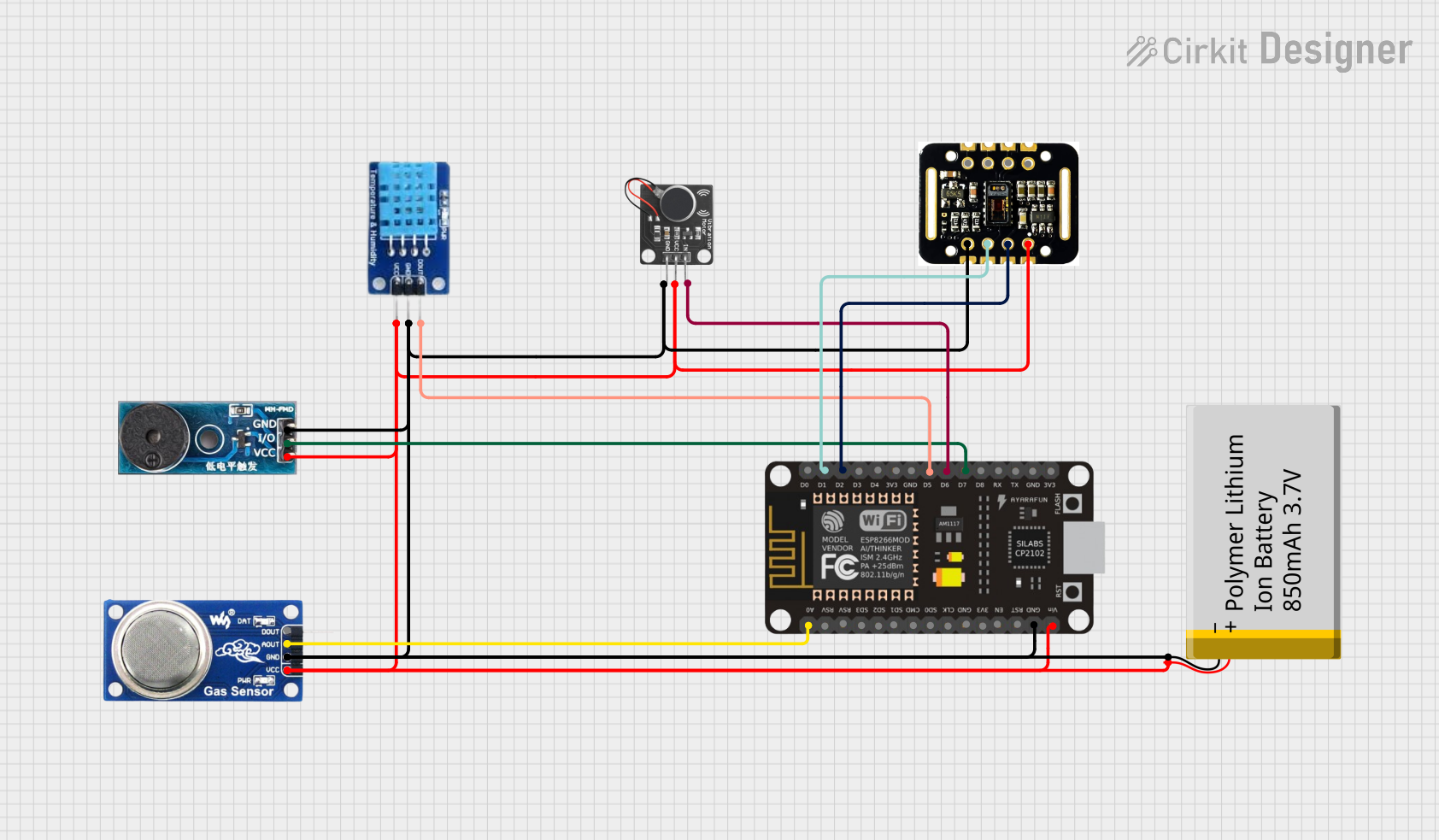
This circuit is designed for environmental monitoring and personal health tracking. It uses an ESP8266 NodeMCU to connect various sensors, including a DHT11 for temperature and humidity, an MQ6 gas sensor for detecting LPG and smoke, a MAX30102 for heart rate and blood oxygen saturation (SpO2) monitoring, and a buzzer and vibration motor for alerts. The system interfaces with the Blynk platform for remote data visualization and can trigger alerts based on sensor readings, such as excessive temperature or gas levels.
ESP32-Based Environmental Monitoring and Weight Detection System with Camera and Display
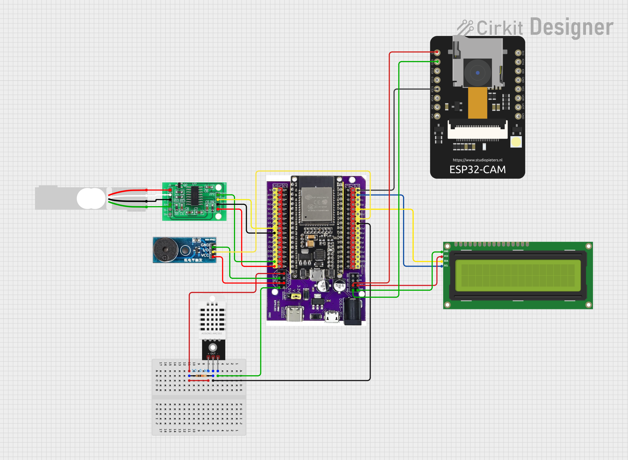
This circuit features an ESP32 on a baseboard as the central microcontroller, interfaced with various peripherals. It includes a DHT22 sensor for measuring temperature and humidity, an I2C LCD screen for display, a buzzer for audio alerts, and an ESP32 CAM module for capturing images or video. Additionally, the circuit integrates an HX711 bridge sensor interface connected to a load cell for weight measurement, with a 10k Ohm resistor for the DHT22 pull-up configuration.
ESP8266 NodeMCU Controlled Environment Monitoring System with Stepper Motor and Sensors
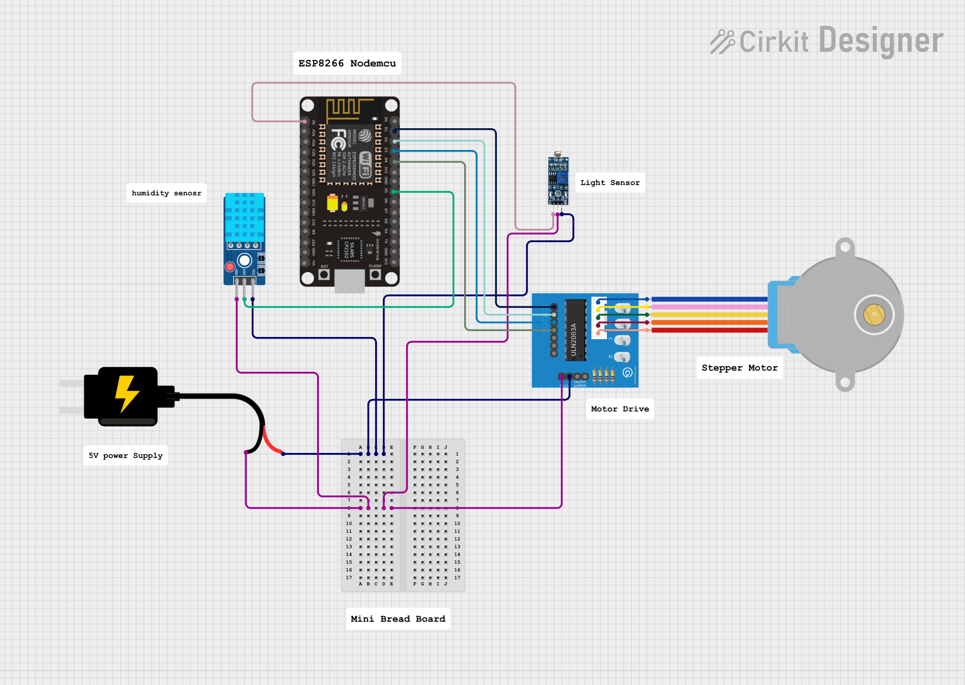
This circuit features an ESP8266 NodeMCU microcontroller connected to a ULN2003A breakout board to drive a 28BYJ-48 stepper motor. The ESP8266 also interfaces with a DHT11 temperature and humidity sensor and an LDR (light-dependent resistor) module for environmental sensing. Power is supplied by a 5V DC source, which is distributed to the motor driver, sensors, and the microcontroller.
ESP8266 and SIM800L Based GPS Tracker with I2C LCD Display and Battery Power

This circuit integrates an ESP8266 NodeMCU microcontroller with a SIM800L GSM module, a GPS NEO 6M module, and a 16x2 I2C LCD display for communication and location tracking. It also includes a pushbutton for user input, a piezo buzzer for audio alerts, and is powered by a 2x 18650 battery pack through an LM2596 step-down module.
Explore Projects Built with esp8266 custom board
ESP8266 NodeMCU-Based Environmental Monitoring System with Wi-Fi Connectivity
This circuit is designed for environmental monitoring and personal health tracking. It uses an ESP8266 NodeMCU to connect various sensors, including a DHT11 for temperature and humidity, an MQ6 gas sensor for detecting LPG and smoke, a MAX30102 for heart rate and blood oxygen saturation (SpO2) monitoring, and a buzzer and vibration motor for alerts. The system interfaces with the Blynk platform for remote data visualization and can trigger alerts based on sensor readings, such as excessive temperature or gas levels.
ESP32-Based Environmental Monitoring and Weight Detection System with Camera and Display
This circuit features an ESP32 on a baseboard as the central microcontroller, interfaced with various peripherals. It includes a DHT22 sensor for measuring temperature and humidity, an I2C LCD screen for display, a buzzer for audio alerts, and an ESP32 CAM module for capturing images or video. Additionally, the circuit integrates an HX711 bridge sensor interface connected to a load cell for weight measurement, with a 10k Ohm resistor for the DHT22 pull-up configuration.
ESP8266 NodeMCU Controlled Environment Monitoring System with Stepper Motor and Sensors
This circuit features an ESP8266 NodeMCU microcontroller connected to a ULN2003A breakout board to drive a 28BYJ-48 stepper motor. The ESP8266 also interfaces with a DHT11 temperature and humidity sensor and an LDR (light-dependent resistor) module for environmental sensing. Power is supplied by a 5V DC source, which is distributed to the motor driver, sensors, and the microcontroller.
ESP8266 and SIM800L Based GPS Tracker with I2C LCD Display and Battery Power
This circuit integrates an ESP8266 NodeMCU microcontroller with a SIM800L GSM module, a GPS NEO 6M module, and a 16x2 I2C LCD display for communication and location tracking. It also includes a pushbutton for user input, a piezo buzzer for audio alerts, and is powered by a 2x 18650 battery pack through an LM2596 step-down module.
Technical Specifications
Key Technical Details
| Parameter | Value |
|---|---|
| Operating Voltage | 3.3V |
| Input Voltage | 5V (via USB) |
| Digital I/O Pins | 11 |
| Analog Input Pins | 1 (10-bit ADC) |
| Flash Memory | 4MB |
| Wi-Fi Standard | 802.11 b/g/n |
| Frequency Range | 2.4 GHz |
| Power Consumption | 170 mA (max) |
| Operating Temperature | -40°C to 125°C |
Pin Configuration and Descriptions
| Pin Number | Pin Name | Description |
|---|---|---|
| 1 | GND | Ground |
| 2 | 3V3 | 3.3V Power Supply |
| 3 | RST | Reset |
| 4 | EN | Chip Enable (Active High) |
| 5 | TX | UART Transmit |
| 6 | RX | UART Receive |
| 7 | GPIO0 | General Purpose I/O 0 |
| 8 | GPIO1 | General Purpose I/O 1 |
| 9 | GPIO2 | General Purpose I/O 2 |
| 10 | GPIO3 | General Purpose I/O 3 |
| 11 | GPIO4 | General Purpose I/O 4 |
| 12 | GPIO5 | General Purpose I/O 5 |
| 13 | ADC | Analog to Digital Converter (A0) |
Usage Instructions
How to Use the Component in a Circuit
- Power Supply: Connect the 3V3 pin to a 3.3V power source. If using USB, the board will regulate the 5V input to 3.3V.
- Ground: Connect the GND pin to the ground of your circuit.
- UART Communication: Connect the TX pin to the RX pin of your microcontroller and the RX pin to the TX pin of your microcontroller for serial communication.
- GPIO Pins: Use the GPIO pins for digital input/output operations. These pins can be configured as needed in your code.
- ADC: Connect analog sensors to the ADC pin for analog input readings.
Important Considerations and Best Practices
- Voltage Levels: Ensure that all connected devices operate at 3.3V logic levels to avoid damaging the ESP8266.
- Power Consumption: The ESP8266 can draw significant current, especially during Wi-Fi transmissions. Ensure your power supply can provide at least 500 mA.
- Antenna Placement: For optimal Wi-Fi performance, place the board in an open area, away from metal objects and other sources of interference.
- Firmware Updates: Keep the firmware updated to the latest version to benefit from performance improvements and security patches.
Example Code for Arduino UNO
#include <ESP8266WiFi.h>

// Replace with your network credentials
const char* ssid = "your_SSID";
const char* password = "your_PASSWORD";

void setup() {
  Serial.begin(115200); // Initialize serial communication at 115200 baud
  delay(10);

  // Connect to Wi-Fi network
  Serial.println();
  Serial.print("Connecting to ");
  Serial.println(ssid);

  WiFi.begin(ssid, password);

  while (WiFi.status() != WL_CONNECTED) {
    delay(500);
    Serial.print(".");
  }

  Serial.println("");
  Serial.println("WiFi connected");
  Serial.println("IP address: ");
  Serial.println(WiFi.localIP()); // Print the IP address
}

void loop() {
  // Your main code here
}
Troubleshooting and FAQs
Common Issues Users Might Face
- Wi-Fi Connection Issues: The board may fail to connect to the Wi-Fi network.
- Power Supply Problems: Insufficient power supply can cause the board to reset or malfunction.
- Serial Communication Errors: Incorrect wiring or baud rate settings can lead to communication failures.
Solutions and Tips for Troubleshooting
- Wi-Fi Connection Issues: Ensure the SSID and password are correct. Check for interference from other devices and ensure the router is within range.
- Power Supply Problems: Use a stable power source that can provide at least 500 mA. Avoid using long or thin wires that can cause voltage drops.
- Serial Communication Errors: Verify the TX and RX connections. Ensure the baud rate in the code matches the baud rate set in the serial monitor.
By following this documentation, you should be able to effectively use the ESP8266 Custom Board in your IoT projects and troubleshoot common issues. Happy building!