How to Use Stepper Motor Driver: Examples, Pinouts, and Specs
Introduction
The COVVY TB6600 Stepper Motor Driver is a robust and versatile device designed to control the operation of stepper motors. It works by sending precise electrical pulses to the motor, enabling accurate positioning, speed control, and smooth operation. This driver is compatible with a wide range of stepper motors, making it ideal for applications requiring precision and reliability.
Explore Projects Built with Stepper Motor Driver


Explore Projects Built with Stepper Motor Driver
Common Applications and Use Cases
- CNC machines
- 3D printers
- Robotics
- Automated conveyor systems
- Camera sliders and gimbals
- Industrial automation
Technical Specifications
The following table outlines the key technical details of the COVVY TB6600 Stepper Motor Driver:
| Parameter | Specification |
|---|---|
| Input Voltage Range | 9V to 42V DC |
| Output Current | Adjustable: 0.5A, 1A, 1.5A, 2A, 2.5A, 3A, 3.5A |
| Step Resolution | Full, 1/2, 1/4, 1/8, 1/16 microstepping |
| Control Signal Voltage | 3.3V to 24V |
| Maximum Step Frequency | 200 kHz |
| Operating Temperature | -10°C to +45°C |
| Dimensions | 96mm x 56mm x 33mm |
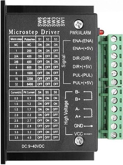
Pin Configuration and Descriptions
The TB6600 Stepper Motor Driver has the following pin configuration:
Input Pins
| Pin Name | Description |
|---|---|
| PUL+ | Pulse signal input (positive terminal) |
| PUL- | Pulse signal input (negative terminal) |
| DIR+ | Direction signal input (positive terminal) |
| DIR- | Direction signal input (negative terminal) |
| ENA+ | Enable signal input (positive terminal) |
| ENA- | Enable signal input (negative terminal) |
Output Pins
| Pin Name | Description |
|---|---|
| A+ | Stepper motor coil A positive terminal |
| A- | Stepper motor coil A negative terminal |
| B+ | Stepper motor coil B positive terminal |
| B- | Stepper motor coil B negative terminal |
Power Pins
| Pin Name | Description |
|---|---|
| VCC | Power supply positive terminal (9V to 42V DC) |
| GND | Power supply ground terminal |
Usage Instructions
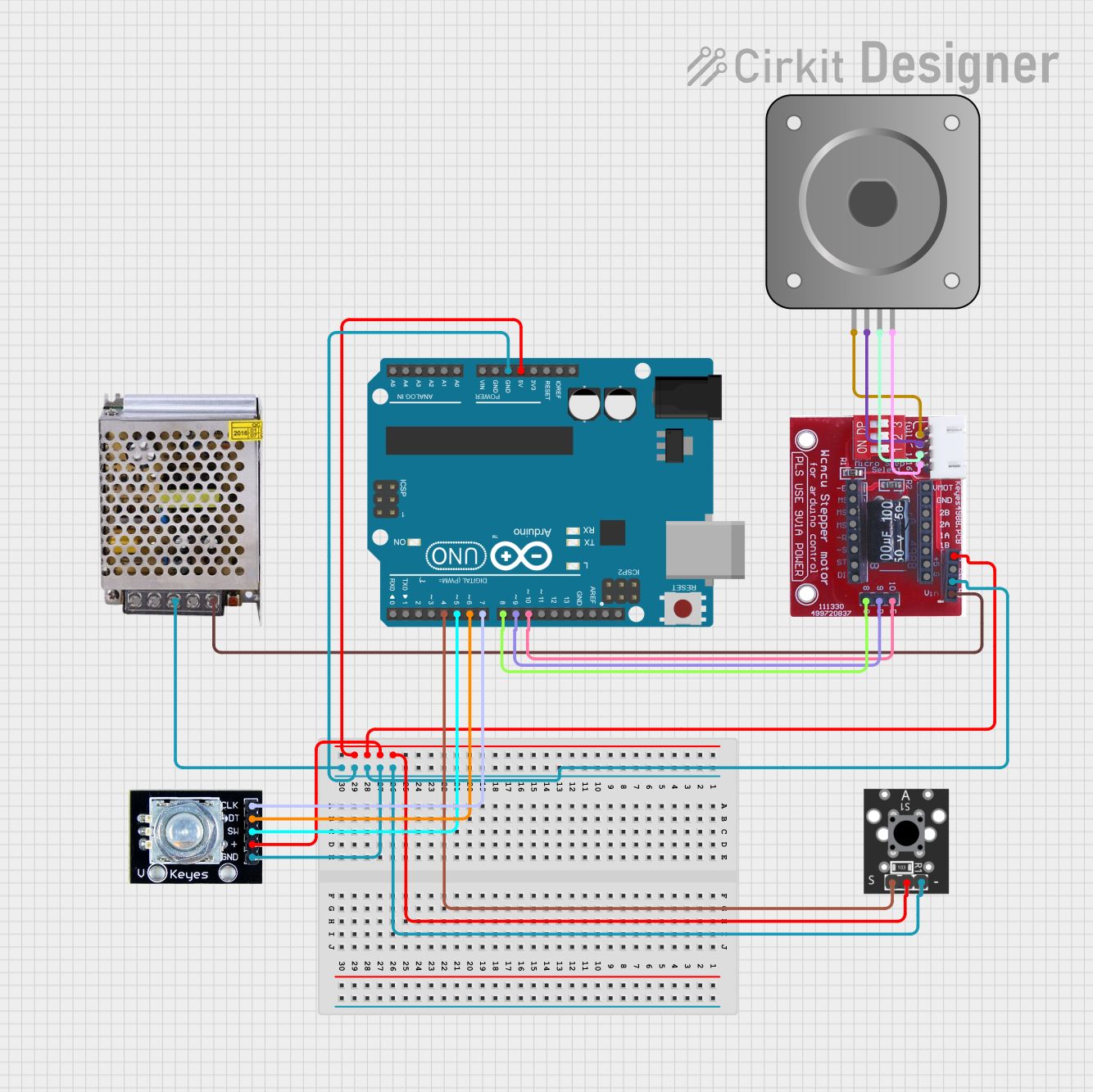
How to Use the Component in a Circuit
Connect the Power Supply:
- Attach the positive terminal of your DC power supply to the
VCCpin and the negative terminal to theGNDpin. Ensure the voltage is within the 9V to 42V range.
- Attach the positive terminal of your DC power supply to the
Connect the Stepper Motor:
- Connect the stepper motor's coil terminals to the
A+,A-,B+, andB-pins. Refer to your motor's datasheet to identify the correct coil pairs.
- Connect the stepper motor's coil terminals to the
Connect Control Signals:
- Use a microcontroller (e.g., Arduino UNO) to send control signals to the
PUL+,PUL-,DIR+,DIR-,ENA+, andENA-pins. Ensure the control signal voltage is between 3.3V and 24V.
- Use a microcontroller (e.g., Arduino UNO) to send control signals to the
Set the Current and Microstepping:
- Use the DIP switches on the driver to configure the desired current limit and microstepping resolution. Refer to the TB6600 datasheet for the DIP switch settings.
Test the Setup:
- Power on the system and send pulse and direction signals from the microcontroller to test the motor's operation.
Important Considerations and Best Practices
- Heat Dissipation: The TB6600 driver can generate heat during operation. Ensure proper ventilation or use a heatsink to prevent overheating.
- Current Settings: Set the current limit according to your stepper motor's rated current to avoid damaging the motor or driver.
- Signal Noise: Use shielded cables for control signals to minimize noise and ensure reliable operation.
- Power Supply: Use a stable and adequately rated power supply to avoid voltage fluctuations.
Example Code for Arduino UNO
Below is an example code to control a stepper motor using the TB6600 driver and an Arduino UNO:
// Define control pins
const int dirPin = 2;  // Direction pin
const int stepPin = 3; // Step pulse pin
const int enPin = 4;   // Enable pin

void setup() {
  // Set pin modes
  pinMode(dirPin, OUTPUT);
  pinMode(stepPin, OUTPUT);
  pinMode(enPin, OUTPUT);

  // Enable the driver
  digitalWrite(enPin, LOW); // LOW to enable the driver
}

void loop() {
  // Set motor direction
  digitalWrite(dirPin, HIGH); // HIGH for clockwise, LOW for counterclockwise

  // Generate step pulses
  for (int i = 0; i < 200; i++) { // 200 steps for one revolution (1.8°/step)
    digitalWrite(stepPin, HIGH);
    delayMicroseconds(500); // Adjust for speed control
    digitalWrite(stepPin, LOW);
    delayMicroseconds(500);
  }

  delay(1000); // Wait 1 second before changing direction

  // Change direction
  digitalWrite(dirPin, LOW);

  // Generate step pulses in the opposite direction
  for (int i = 0; i < 200; i++) {
    digitalWrite(stepPin, HIGH);
    delayMicroseconds(500);
    digitalWrite(stepPin, LOW);
    delayMicroseconds(500);
  }

  delay(1000); // Wait 1 second before repeating
}
Troubleshooting and FAQs
Common Issues and Solutions
Motor Not Moving:
- Cause: Incorrect wiring or loose connections.
- Solution: Double-check all connections, especially the motor coils and control signals.
Driver Overheating:
- Cause: Excessive current or poor ventilation.
- Solution: Reduce the current setting using the DIP switches and ensure proper cooling.
Motor Vibrating but Not Rotating:
- Cause: Incorrect stepper motor wiring.
- Solution: Verify the coil pairs and ensure they are connected to the correct driver terminals.
Inconsistent Motor Movement:
- Cause: Signal noise or unstable power supply.
- Solution: Use shielded cables for control signals and a stable power supply.
FAQs
Q: Can I use the TB6600 with a 5V microcontroller?
A: Yes, the TB6600 supports control signal voltages as low as 3.3V, making it compatible with 5V microcontrollers like Arduino UNO.Q: What is the maximum step frequency supported?
A: The TB6600 supports a maximum step frequency of 200 kHz.Q: How do I select the microstepping resolution?
A: Use the DIP switches on the driver to configure the microstepping resolution. Refer to the TB6600 datasheet for the specific switch settings.Q: Can I use the TB6600 with a NEMA 23 stepper motor?
A: Yes, the TB6600 is compatible with NEMA 23 and other stepper motors within its voltage and current range.