Cirkit Designer
Your all-in-one circuit design IDE
Home /
Component Documentation
How to Use BP sensor: Examples, Pinouts, and Specs
Introduction
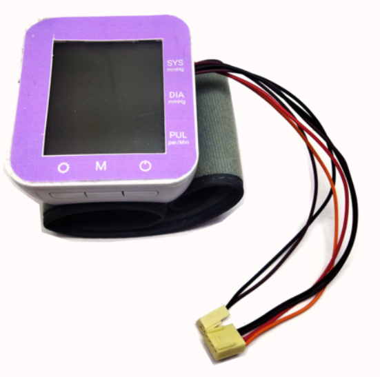
A BP sensor, or blood pressure sensor, is a device used to measure the blood pressure of an individual. It typically consists of a cuff that inflates to constrict the blood flow and sensors that detect the pressure in the arteries. BP sensors are crucial in medical diagnostics and monitoring, providing vital information about cardiovascular health. They are commonly used in hospitals, clinics, and home healthcare settings.
Explore Projects Built with BP sensor
ESP-8266 Based Environmental Monitoring System
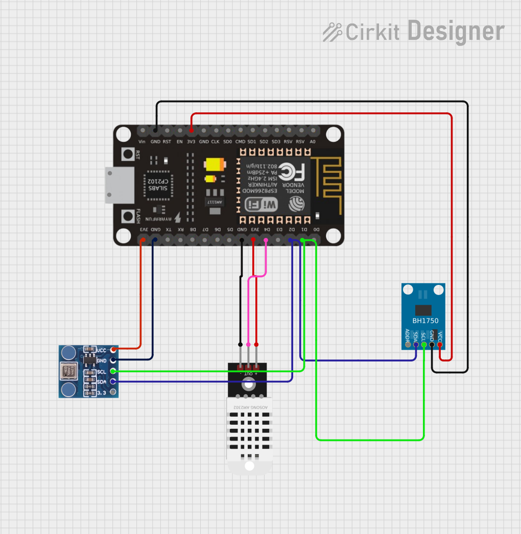
This circuit features an ESP-8266 microcontroller connected to a BMP180 barometric pressure sensor, a BH1750 light intensity sensor, and a DHT22 temperature and humidity sensor. The ESP-8266 uses its I2C interface, with pins D1 and D2 connected to the SCL and SDA lines of both the BMP180 and BH1750, to communicate with the sensors. The DHT22 sensor is connected to a digital pin (D4) for direct signal reading, and all sensors share common power (3V3) and ground (GND) connections with the microcontroller.
ESP32-Based Air Quality Monitoring Station with BMP280, SGP41, and PMS5003 Sensors
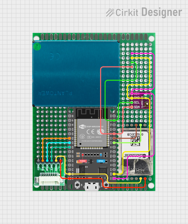
This circuit is designed for environmental sensing and monitoring, featuring multiple sensors including a BMP280 for barometric pressure and temperature, a SenseAir S8 for CO2 levels, a PMS5003 for particulate matter, and an SGP41 for VOC and NOx levels. These sensors are interfaced with an ESP32 microcontroller, which likely serves as the central processing unit to collect, process, and possibly transmit sensor data. The ESP32 is connected to the sensors using I2C (SDA/SCL lines) and serial communication (RX/TX lines), and it provides power to the sensors (3V3/VIN lines).
ESP8266-Based Environmental Monitoring System
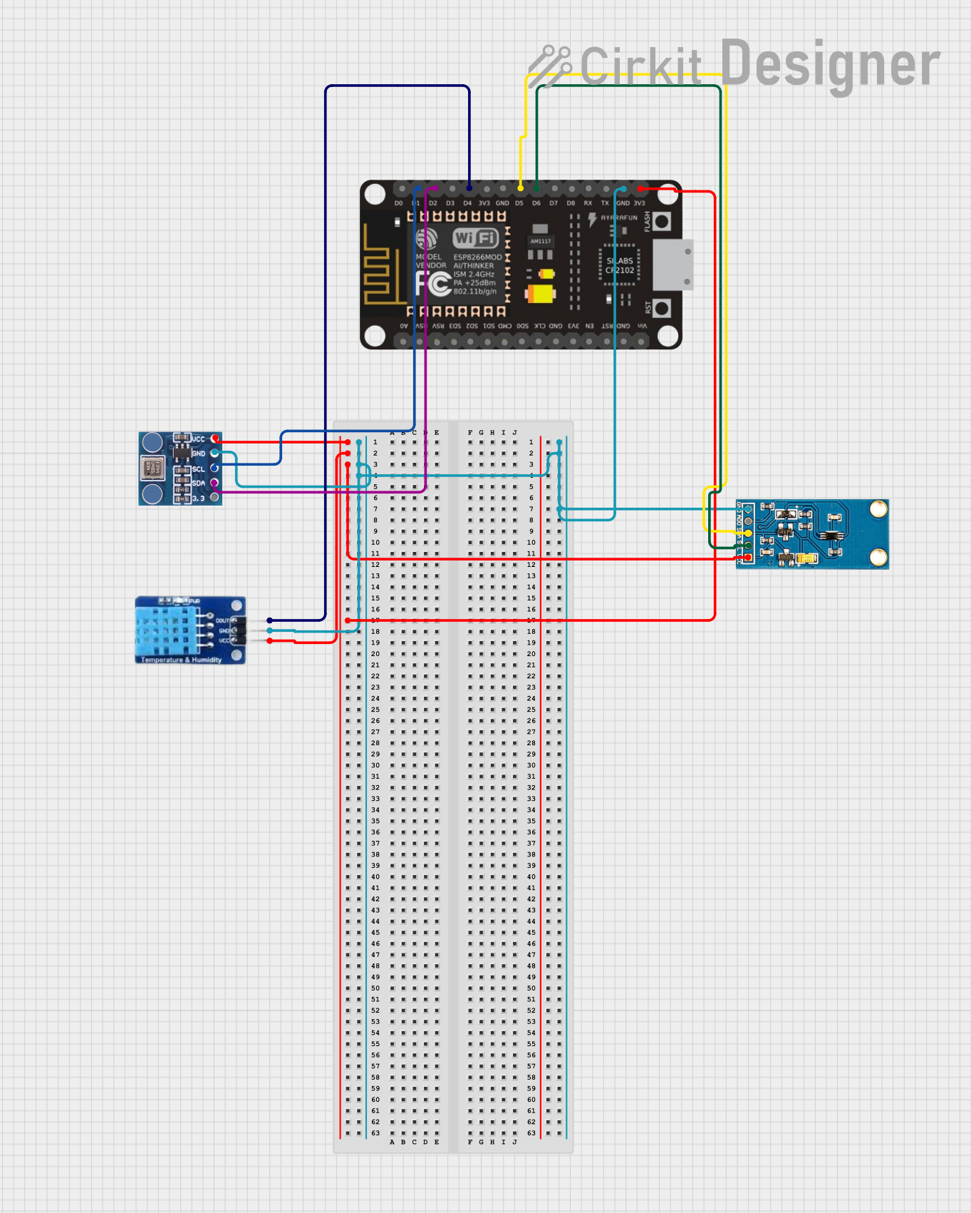
This circuit is designed to collect environmental data using an ESP-8266 microcontroller connected to a BMP180 barometric pressure sensor, a GY-30 BH1750FVI digital light intensity sensor, and a DHT11 temperature and humidity sensor. The sensors are interfaced with the ESP-8266 via I2C (SCL and SDA lines) and digital IO pins, and they share a common power supply (3.3V) and ground. The circuit is likely intended for weather monitoring or home automation applications, with capabilities to measure temperature, humidity, barometric pressure, and light intensity.
ESP32 and INA3221-Based Smart Power Monitoring System with Bluetooth and Environmental Sensing
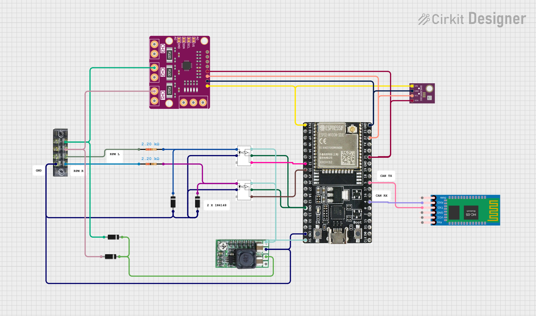
This circuit is a sensor monitoring and communication system that uses an ESP32 microcontroller to read data from a BME/BMP280 environmental sensor and an INA3221 power monitor. The ESP32 communicates with the sensors via I2C and transmits data wirelessly using an HC-05 Bluetooth module. Additionally, the circuit includes optocouplers and diodes for signal isolation and protection.
Explore Projects Built with BP sensor
ESP-8266 Based Environmental Monitoring System
This circuit features an ESP-8266 microcontroller connected to a BMP180 barometric pressure sensor, a BH1750 light intensity sensor, and a DHT22 temperature and humidity sensor. The ESP-8266 uses its I2C interface, with pins D1 and D2 connected to the SCL and SDA lines of both the BMP180 and BH1750, to communicate with the sensors. The DHT22 sensor is connected to a digital pin (D4) for direct signal reading, and all sensors share common power (3V3) and ground (GND) connections with the microcontroller.
ESP32-Based Air Quality Monitoring Station with BMP280, SGP41, and PMS5003 Sensors
This circuit is designed for environmental sensing and monitoring, featuring multiple sensors including a BMP280 for barometric pressure and temperature, a SenseAir S8 for CO2 levels, a PMS5003 for particulate matter, and an SGP41 for VOC and NOx levels. These sensors are interfaced with an ESP32 microcontroller, which likely serves as the central processing unit to collect, process, and possibly transmit sensor data. The ESP32 is connected to the sensors using I2C (SDA/SCL lines) and serial communication (RX/TX lines), and it provides power to the sensors (3V3/VIN lines).
ESP8266-Based Environmental Monitoring System
This circuit is designed to collect environmental data using an ESP-8266 microcontroller connected to a BMP180 barometric pressure sensor, a GY-30 BH1750FVI digital light intensity sensor, and a DHT11 temperature and humidity sensor. The sensors are interfaced with the ESP-8266 via I2C (SCL and SDA lines) and digital IO pins, and they share a common power supply (3.3V) and ground. The circuit is likely intended for weather monitoring or home automation applications, with capabilities to measure temperature, humidity, barometric pressure, and light intensity.
ESP32 and INA3221-Based Smart Power Monitoring System with Bluetooth and Environmental Sensing
This circuit is a sensor monitoring and communication system that uses an ESP32 microcontroller to read data from a BME/BMP280 environmental sensor and an INA3221 power monitor. The ESP32 communicates with the sensors via I2C and transmits data wirelessly using an HC-05 Bluetooth module. Additionally, the circuit includes optocouplers and diodes for signal isolation and protection.
Technical Specifications
Key Technical Details
| Parameter | Value |
|---|---|
| Operating Voltage | 3.3V - 5V |
| Operating Current | 10mA |
| Pressure Range | 0 - 300 mmHg |
| Accuracy | ±3 mmHg |
| Interface | I2C |
| Temperature Range | 0°C to 50°C |
Pin Configuration and Descriptions
| Pin Number | Pin Name | Description |
|---|---|---|
| 1 | VCC | Power supply (3.3V - 5V) |
| 2 | GND | Ground |
| 3 | SDA | I2C data line |
| 4 | SCL | I2C clock line |
| 5 | INT | Interrupt output (optional) |
Usage Instructions
How to Use the Component in a Circuit
- Power Supply: Connect the VCC pin to a 3.3V or 5V power supply and the GND pin to the ground.
- I2C Communication: Connect the SDA pin to the SDA pin on the microcontroller (e.g., Arduino UNO) and the SCL pin to the SCL pin on the microcontroller.
- Interrupt (Optional): If using the interrupt feature, connect the INT pin to a digital input pin on the microcontroller.
Important Considerations and Best Practices
- Calibration: Ensure the BP sensor is calibrated according to the manufacturer's instructions for accurate readings.
- Cuff Placement: Place the cuff correctly on the arm, ensuring it is snug but not too tight.
- Environmental Conditions: Use the sensor within the specified temperature range (0°C to 50°C) to avoid inaccurate readings.
- Power Supply: Use a stable power supply to prevent fluctuations that could affect sensor performance.
Sample Arduino Code
#include <Wire.h>

#define BP_SENSOR_ADDR 0x40 // Replace with the actual I2C address of your BP sensor

void setup() {
  Serial.begin(9600);
  Wire.begin(); // Initialize I2C communication
}

void loop() {
  Wire.beginTransmission(BP_SENSOR_ADDR);
  Wire.write(0x00); // Command to read blood pressure data
  Wire.endTransmission();

  Wire.requestFrom(BP_SENSOR_ADDR, 2); // Request 2 bytes from the sensor
  if (Wire.available() == 2) {
    int pressure = Wire.read() << 8 | Wire.read(); // Combine the two bytes
    Serial.print("Blood Pressure: ");
    Serial.print(pressure);
    Serial.println(" mmHg");
  }

  delay(1000); // Wait for 1 second before the next reading
}
Troubleshooting and FAQs
Common Issues Users Might Face
- No Data Output: Ensure all connections are secure and the power supply is stable.
- Inaccurate Readings: Check the cuff placement and ensure the sensor is calibrated.
- I2C Communication Errors: Verify the I2C address and ensure there are no address conflicts on the bus.
Solutions and Tips for Troubleshooting
- Check Connections: Double-check all wiring and connections to ensure they are correct and secure.
- Verify Power Supply: Ensure the sensor is receiving the correct voltage and current.
- Recalibrate: If readings are inaccurate, recalibrate the sensor according to the manufacturer's instructions.
- Use Pull-up Resistors: If experiencing I2C communication issues, try adding pull-up resistors (4.7kΩ) to the SDA and SCL lines.
By following this documentation, users should be able to effectively integrate and utilize the BP sensor in their projects, ensuring accurate and reliable blood pressure measurements.