How to Use RELAY 3.3V: Examples, Pinouts, and Specs
Introduction
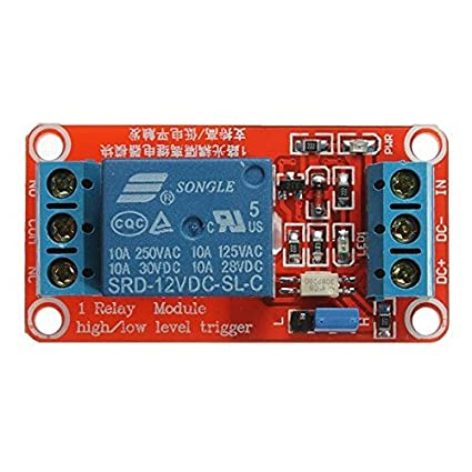
The RELAY 3.3V, manufactured by ESP32, is an electromechanical switch designed to control high voltage or high current devices using a low voltage signal. It operates at a control voltage of 3.3V, making it ideal for integration with microcontrollers like the ESP32 or Arduino. The relay provides electrical isolation between the control circuit and the load, ensuring safety and reliability in various applications.
Explore Projects Built with RELAY 3.3V


Explore Projects Built with RELAY 3.3V
Common Applications and Use Cases
- Home automation systems (e.g., controlling lights, fans, or appliances)
- Industrial control systems
- Motor control
- IoT projects requiring electrical isolation
- Switching high-power devices with low-power microcontrollers
Technical Specifications
The following table outlines the key technical details of the RELAY 3.3V:
| Parameter | Value |
|---|---|
| Operating Voltage | 3.3V DC |
| Trigger Current | ~70mA |
| Contact Voltage Rating | Up to 250V AC / 30V DC |
| Contact Current Rating | Up to 10A |
| Relay Type | SPDT (Single Pole Double Throw) |
| Electrical Isolation | Optocoupler-based isolation |
| Dimensions | 28mm x 12mm x 10mm |
| Operating Temperature | -40°C to 85°C |
Pin Configuration and Descriptions
The RELAY 3.3V typically has the following pin configuration:
| Pin Name | Description |
|---|---|
| VCC | Connect to 3.3V power supply. This powers the relay's internal circuitry. |
| GND | Connect to ground. |
| IN | Control signal input. A HIGH signal (3.3V) activates the relay. |
| COM | Common terminal for the relay's switch. |
| NO | Normally Open terminal. Connect the load here if it should be OFF by default. |
| NC | Normally Closed terminal. Connect the load here if it should be ON by default. |
Usage Instructions
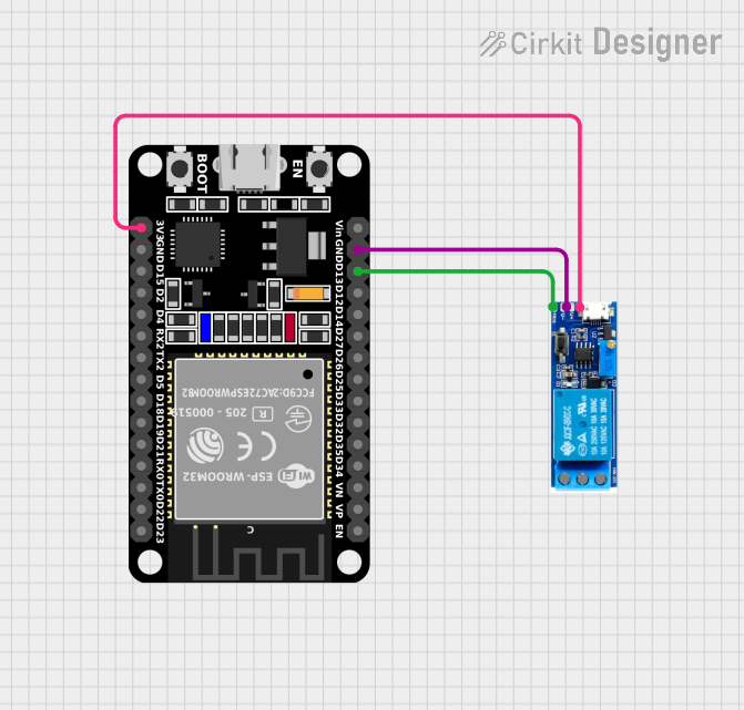
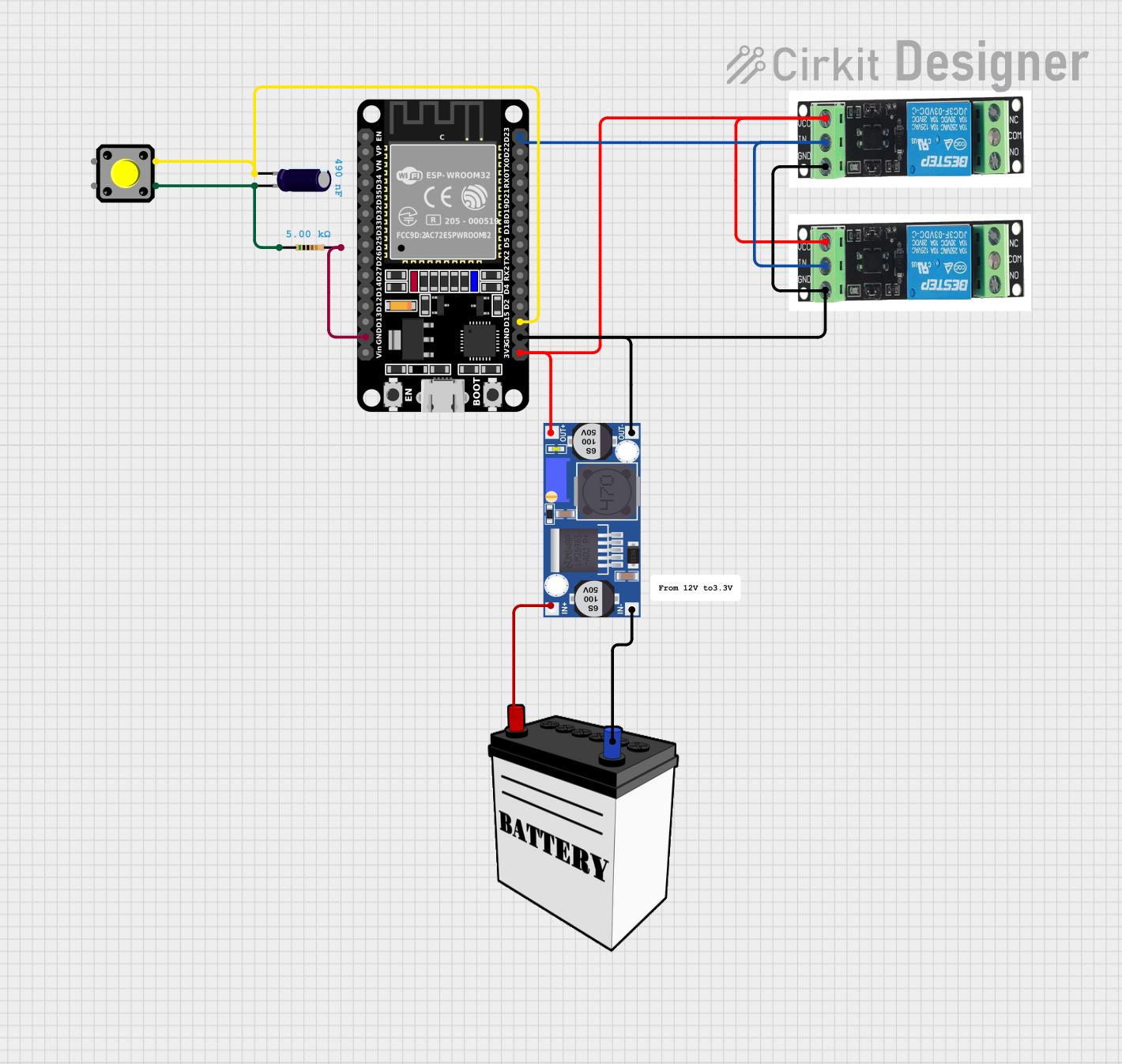
How to Use the RELAY 3.3V in a Circuit
- Power the Relay: Connect the VCC pin to a 3.3V power source and the GND pin to ground.
- Control Signal: Connect the IN pin to a GPIO pin of your microcontroller (e.g., ESP32 or Arduino). When the GPIO pin outputs a HIGH signal (3.3V), the relay will activate.
- Load Connection:
- Connect the load's power source to the COM terminal.
- Connect the load to either the NO (Normally Open) or NC (Normally Closed) terminal, depending on the desired default state of the load.
- Isolation: Ensure the control circuit and load circuit are electrically isolated for safety.
Important Considerations and Best Practices
- Flyback Diode: If you're using an inductive load (e.g., a motor), add a flyback diode across the load to protect the relay from voltage spikes.
- Current Rating: Ensure the load's current does not exceed the relay's maximum current rating (10A).
- Signal Voltage: The control signal must be 3.3V. Higher voltages may damage the relay.
- Mounting: Secure the relay on a PCB or use a relay module for easier integration.
Example: Connecting RELAY 3.3V to an Arduino UNO
Below is an example of how to control the RELAY 3.3V using an Arduino UNO:
// Define the pin connected to the relay's IN pin
const int relayPin = 7;

void setup() {
  // Set the relay pin as an output
  pinMode(relayPin, OUTPUT);

  // Ensure the relay is OFF at startup
  digitalWrite(relayPin, LOW);
}

void loop() {
  // Turn the relay ON
  digitalWrite(relayPin, HIGH);
  delay(5000); // Keep the relay ON for 5 seconds

  // Turn the relay OFF
  digitalWrite(relayPin, LOW);
  delay(5000); // Keep the relay OFF for 5 seconds
}
Notes:
- Connect the relay's IN pin to Arduino pin 7.
- Ensure the Arduino's 5V output is stepped down to 3.3V if directly powering the relay.
Troubleshooting and FAQs
Common Issues and Solutions
Relay Not Activating:
- Cause: Insufficient control voltage or current.
- Solution: Verify that the control signal is 3.3V and the power supply can provide sufficient current (~70mA).
Load Not Switching:
- Cause: Incorrect wiring of the load to the relay terminals.
- Solution: Double-check the connections to the COM, NO, and NC terminals.
Relay Stuck in One State:
- Cause: Damaged relay contacts due to overcurrent or arcing.
- Solution: Replace the relay and ensure the load does not exceed the rated current.
Microcontroller Resetting When Relay Activates:
- Cause: Voltage spikes or insufficient power supply.
- Solution: Add a flyback diode across the load and ensure the power supply is stable.
FAQs
Q1: Can I use the RELAY 3.3V with a 5V microcontroller?
A1: Yes, but you must use a level shifter or resistor divider to step down the 5V control signal to 3.3V.
Q2: Is the relay suitable for AC loads?
A2: Yes, the relay can handle AC loads up to 250V, provided the current does not exceed 10A.
Q3: Can I control multiple relays with one microcontroller?
A3: Yes, as long as each relay is connected to a separate GPIO pin and the microcontroller can supply sufficient current.
Q4: Does the relay make a clicking sound when switching?
A4: Yes, the clicking sound is normal and indicates the mechanical switch inside the relay is operating.