Cirkit Designer Logo
Cirkit Designer
Your all-in-one circuit design IDE
Home / 
Component Documentation

How to Use ESP32: Examples, Pinouts, and Specs

Image of ESP32
Cirkit Designer LogoDesign with ESP32 in Cirkit Designer

Introduction

The ESP32, manufactured by THINGS KIT as the MINI NODEMCU variant, is a powerful System on Chip (SoC) microcontroller that offers a rich set of features including Wi-Fi and Bluetooth connectivity. This makes it an ideal choice for a wide range of applications, particularly in the Internet of Things (IoT) domain, where wireless connectivity and low power consumption are crucial. Common applications include smart home devices, wearable electronics, wireless sensors, and a variety of automation projects.

Explore Projects Built with ESP32

Use Cirkit Designer to design, explore, and prototype these projects online. Some projects support real-time simulation. Click "Open Project" to start designing instantly!
ESP32-Based Sensor Monitoring System with OLED Display and E-Stop
Image of MVP_design: A project utilizing ESP32 in a practical application
This circuit features an ESP32 microcontroller that interfaces with a variety of sensors and output devices. It is powered by a Lipo battery through a buck converter, ensuring a stable voltage supply. The ESP32 collects data from a DHT11 temperature and humidity sensor and a vibration sensor, controls a buzzer, and displays information on an OLED screen. An emergency stop (E Stop) is connected for safety purposes, allowing the system to be quickly deactivated.
Cirkit Designer LogoOpen Project in Cirkit Designer
ESP32-Based NTP Clock with DHT22 Temperature Sensor and WS2812 LED Matrix Display
Image of date time and temperature display : A project utilizing ESP32 in a practical application
This circuit features an ESP32 Devkit V1 microcontroller connected to a DHT22 temperature and humidity sensor and an 8x8 WS2812 RGB LED matrix. The ESP32 reads temperature data from the DHT22 sensor and displays the current date, time, and temperature on the LED matrix, with date and time synchronized via NTP (Network Time Protocol). The ESP32 provides power to both the DHT22 and the LED matrix and communicates with the DHT22 via GPIO 4 and with the LED matrix via GPIO 5.
Cirkit Designer LogoOpen Project in Cirkit Designer
ESP32-Based Environmental Monitoring System with Water Flow Sensing
Image of Water: A project utilizing ESP32 in a practical application
This circuit features an ESP32 Devkit V1 microcontroller connected to a DHT22 temperature and humidity sensor and a water flow sensor. The ESP32 reads environmental data from the DHT22 via a digital input pin (D33) and monitors water flow through the water flow sensor connected to another digital input pin (D23). The ESP32 is powered through its VIN pin, and both sensors are powered by the ESP32's 3V3 output, with common ground connections.
Cirkit Designer LogoOpen Project in Cirkit Designer
ESP32-Based Smart Weather Station with Wi-Fi Connectivity
Image of flowchart 3D: A project utilizing ESP32 in a practical application
This circuit features an ESP32 microcontroller interfacing with various sensors and modules, including a DHT22 temperature and humidity sensor, an ESP32 CAM for image capture, an I2C LCD screen for display, a load cell with an HX711 interface for weight measurement, and a buzzer for audio alerts. The ESP32 handles data acquisition, processing, and communication with these peripherals to create a multi-functional monitoring and alert system.
Cirkit Designer LogoOpen Project in Cirkit Designer

Explore Projects Built with ESP32

Use Cirkit Designer to design, explore, and prototype these projects online. Some projects support real-time simulation. Click "Open Project" to start designing instantly!
Image of MVP_design: A project utilizing ESP32 in a practical application
ESP32-Based Sensor Monitoring System with OLED Display and E-Stop
This circuit features an ESP32 microcontroller that interfaces with a variety of sensors and output devices. It is powered by a Lipo battery through a buck converter, ensuring a stable voltage supply. The ESP32 collects data from a DHT11 temperature and humidity sensor and a vibration sensor, controls a buzzer, and displays information on an OLED screen. An emergency stop (E Stop) is connected for safety purposes, allowing the system to be quickly deactivated.
Cirkit Designer LogoOpen Project in Cirkit Designer
Image of date time and temperature display : A project utilizing ESP32 in a practical application
ESP32-Based NTP Clock with DHT22 Temperature Sensor and WS2812 LED Matrix Display
This circuit features an ESP32 Devkit V1 microcontroller connected to a DHT22 temperature and humidity sensor and an 8x8 WS2812 RGB LED matrix. The ESP32 reads temperature data from the DHT22 sensor and displays the current date, time, and temperature on the LED matrix, with date and time synchronized via NTP (Network Time Protocol). The ESP32 provides power to both the DHT22 and the LED matrix and communicates with the DHT22 via GPIO 4 and with the LED matrix via GPIO 5.
Cirkit Designer LogoOpen Project in Cirkit Designer
Image of Water: A project utilizing ESP32 in a practical application
ESP32-Based Environmental Monitoring System with Water Flow Sensing
This circuit features an ESP32 Devkit V1 microcontroller connected to a DHT22 temperature and humidity sensor and a water flow sensor. The ESP32 reads environmental data from the DHT22 via a digital input pin (D33) and monitors water flow through the water flow sensor connected to another digital input pin (D23). The ESP32 is powered through its VIN pin, and both sensors are powered by the ESP32's 3V3 output, with common ground connections.
Cirkit Designer LogoOpen Project in Cirkit Designer
Image of flowchart 3D: A project utilizing ESP32 in a practical application
ESP32-Based Smart Weather Station with Wi-Fi Connectivity
This circuit features an ESP32 microcontroller interfacing with various sensors and modules, including a DHT22 temperature and humidity sensor, an ESP32 CAM for image capture, an I2C LCD screen for display, a load cell with an HX711 interface for weight measurement, and a buzzer for audio alerts. The ESP32 handles data acquisition, processing, and communication with these peripherals to create a multi-functional monitoring and alert system.
Cirkit Designer LogoOpen Project in Cirkit Designer

Technical Specifications

Key Technical Details

  • Microcontroller: Tensilica Xtensa® Dual-Core 32-bit LX6 microprocessor
  • Operating Voltage: 3.3V
  • Input Voltage: 7-12V
  • Digital I/O Pins: 22
  • Analog Input Pins: 6 (ADC 12-bit)
  • Analog Output Pins: 2 (DAC 10-bit)
  • Wi-Fi: 802.11 b/g/n
  • Bluetooth: v4.2 BR/EDR and BLE
  • Flash Memory: 4MB
  • SRAM: 520 KB
  • Clock Speed: Up to 240MHz

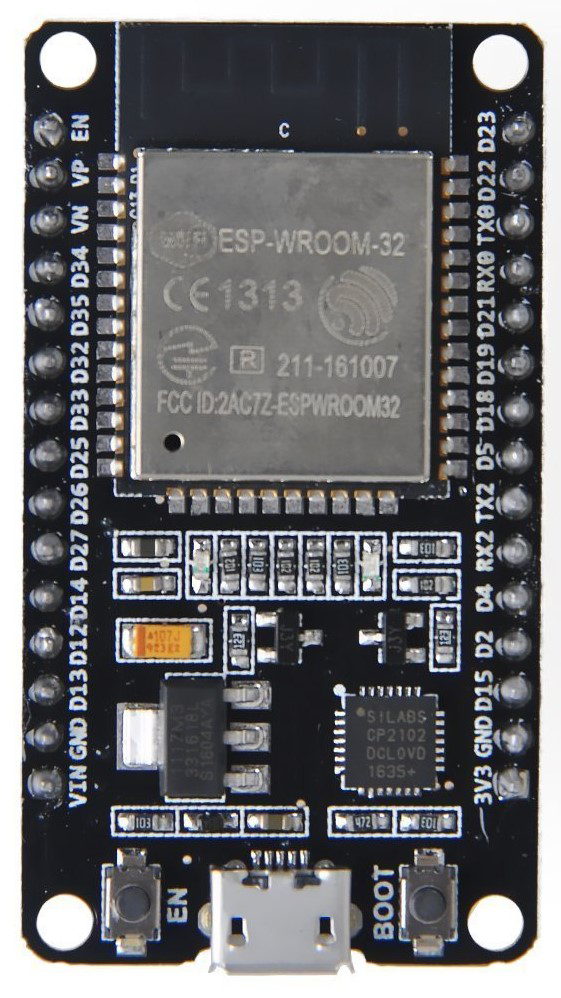
Pin Configuration and Descriptions

Pin Number Function Description
1 3V3 3.3V power supply
2 GND Ground
3 EN Reset pin (active low)
4 VP GPIO36, ADC1_CH0, Sensor VP
5 VN GPIO39, ADC1_CH3, Sensor VN
... ... ...
36 IO34 GPIO34, ADC1_CH6, Input only
37 IO35 GPIO35, ADC1_CH7, Input only
38 IO32 GPIO32, ADC1_CH4, XTAL_32K_P (32.768 kHz XTAL oscillator input)
39 IO33 GPIO33, ADC1_CH5, XTAL_32K_N (32.768 kHz XTAL oscillator output)
... ... ...

Note: This table is not exhaustive and only includes a selection of pins. Please refer to the manufacturer's datasheet for the complete pinout.

Usage Instructions

Integrating with a Circuit

To use the ESP32 in a circuit:

  1. Connect the power supply to the VIN (7-12V) and GND pins for operation.
  2. Ensure that the EN pin is connected to a high logic level for normal operation.
  3. Interface with the GPIO pins as required for your application, taking care to respect the maximum current ratings.

Best Practices

  • Use a stable power supply to prevent unexpected resets.
  • Avoid exposing the pins to voltages higher than 3.3V to prevent damage.
  • Utilize the deep sleep mode for battery-powered applications to conserve energy.
  • Ensure proper antenna placement for optimal Wi-Fi and Bluetooth performance.

Example Code for Arduino UNO

#include <WiFi.h>

// Replace with your network credentials
const char* ssid = "your_SSID";
const char* password = "your_PASSWORD";

void setup() {
  Serial.begin(115200);
  // Connect to Wi-Fi
  WiFi.begin(ssid, password);
  while (WiFi.status() != WL_CONNECTED) {
    delay(500);
    Serial.println("Connecting to WiFi...");
  }
  Serial.println("Connected to WiFi");
}

void loop() {
  // Put your main code here, to run repeatedly:
}

Note: This code is for connecting the ESP32 to a Wi-Fi network. The ESP32 is programmed using the Arduino IDE, but it is not connected to an Arduino UNO for this operation.

Troubleshooting and FAQs

Common Issues

  • Failure to Connect to Wi-Fi: Ensure the SSID and password are correct. Check the signal strength and router settings.
  • Unexpected Resets: Verify the power supply is stable and within the specified range.
  • GPIO Malfunction: Ensure that the pins are not being driven with voltages higher than 3.3V and that the current limits are not exceeded.

Solutions and Tips

  • Wi-Fi Connectivity: Place the ESP32 closer to the router or use an external antenna for better signal strength.
  • Power Supply Issues: Use a regulated power supply and add capacitors to filter out noise.
  • Pin Voltage Levels: Use level shifters for interfacing with components that operate at different voltage levels.

FAQs

Q: Can the ESP32 be used with the Arduino IDE? A: Yes, the ESP32 can be programmed using the Arduino IDE by installing the appropriate board manager.

Q: What is the maximum current that the GPIO pins can handle? A: The maximum current per GPIO pin is 12 mA.

Q: Does the ESP32 support Over-The-Air (OTA) programming? A: Yes, the ESP32 supports OTA updates, allowing for wireless uploading of new code.

For more detailed troubleshooting, refer to the manufacturer's documentation and community forums dedicated to ESP32 development.