How to Use 12v PWM Fan (120mm): Examples, Pinouts, and Specs
Introduction
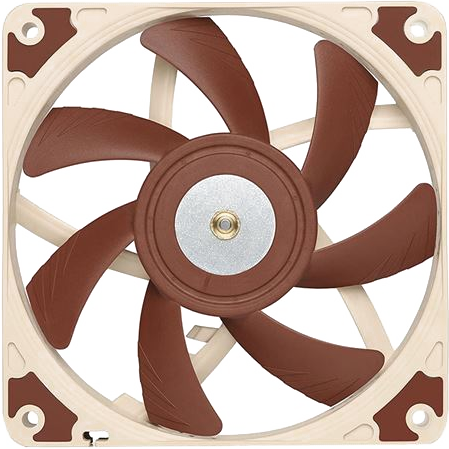
The 12V PWM Fan (120mm) is an essential component in thermal management and cooling systems. It is designed to operate with a 12V power supply and utilizes Pulse-Width Modulation (PWM) for precise control over its speed. This fan is commonly used in computer cases, power supplies, and other electronics that require active cooling to maintain optimal operating temperatures.
Explore Projects Built with 12v PWM Fan (120mm)

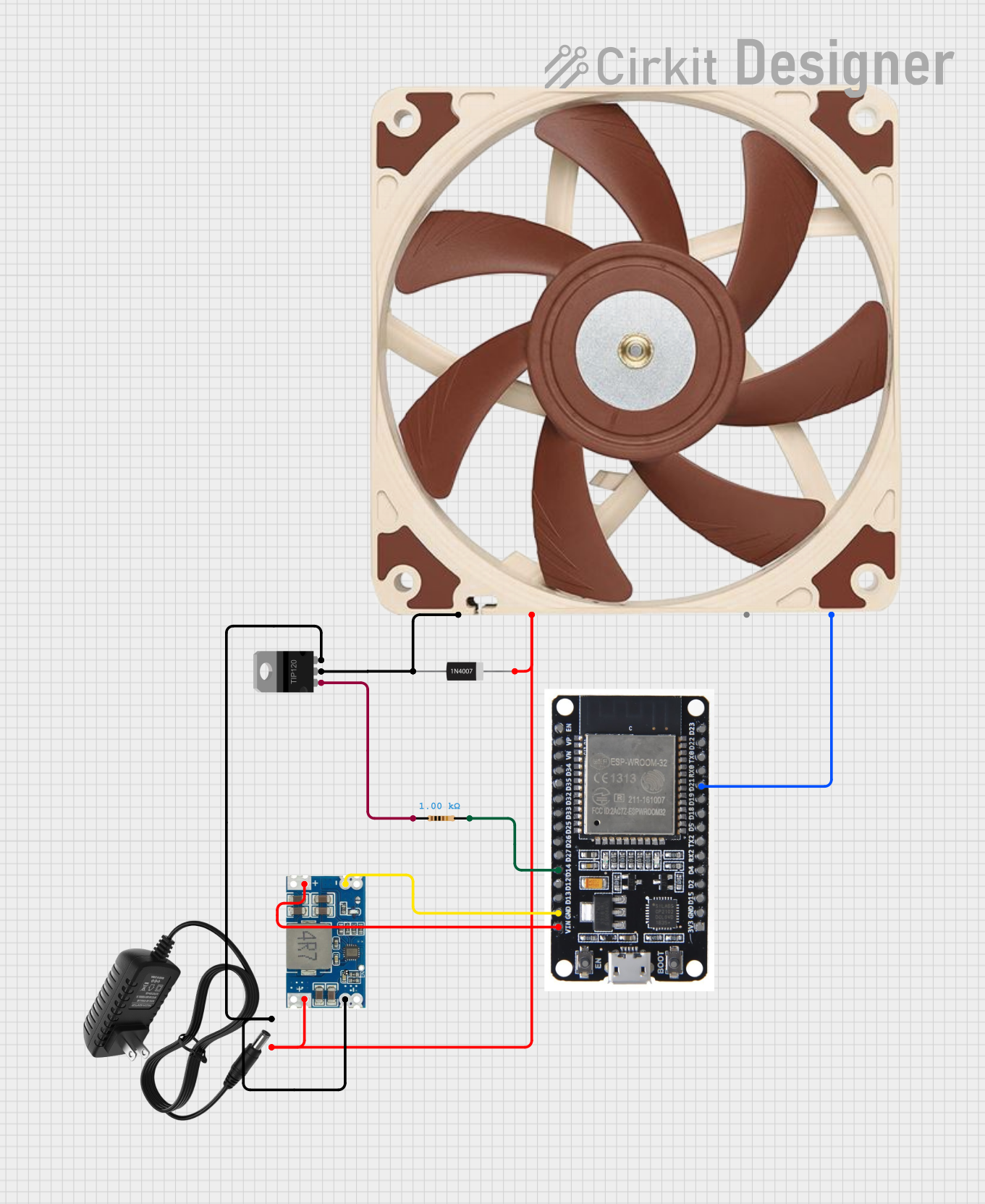
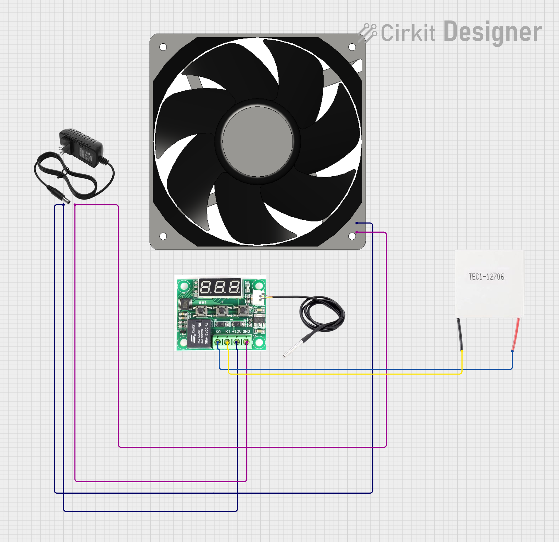
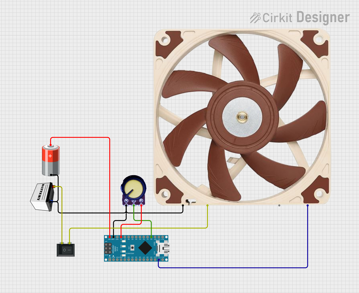
Explore Projects Built with 12v PWM Fan (120mm)
Common Applications and Use Cases
- Computer case cooling
- Power supply units
- Electronic enclosures
- Heat exchangers
- Ventilation systems
Technical Specifications
Key Technical Details
| Specification | Value |
|---|---|
| Operating Voltage | 12V DC |
| Size | 120mm x 120mm |
| Speed Control | PWM |
| Airflow | XX CFM |
| Noise Level | XX dB(A) |
| Bearing Type | Sleeve/Ball |
| Connector Type | 4-pin |
Pin Configuration and Descriptions
| Pin Number | Description |
|---|---|
| 1 | Ground |
| 2 | +12V Power Supply |
| 3 | Tachometer Signal |
| 4 | PWM Control Signal |
Usage Instructions
How to Use the Component in a Circuit
- Power Connection: Connect pin 2 to a 12V power source and pin 1 to the ground.
- PWM Control: To control the fan speed, apply a PWM signal to pin 4. The duty cycle of the PWM signal will determine the fan speed.
- Tachometer Reading: Pin 3 outputs a tachometer signal that can be used to monitor the fan's speed.
Important Considerations and Best Practices
- Ensure that the power supply can handle the current requirements of the fan.
- Use a PWM controller or a microcontroller like an Arduino UNO to generate the PWM signal.
- Avoid running the fan at full speed for extended periods to prolong its lifespan.
- Keep the fan blades and surrounding area clean to maintain optimal performance.
Example Code for Arduino UNO
// Define the PWM pin connected to the fan
const int pwmPin = 9; // The PWM pin the fan is attached to

void setup() {
  // Configure the PWM pin as an output
  pinMode(pwmPin, OUTPUT);
}

void loop() {
  // Set the fan speed to 50% duty cycle
  analogWrite(pwmPin, 127); // 127 out of 255 is approximately 50%
  delay(5000); // Run the fan at this speed for 5 seconds

  // Increase the fan speed to 75% duty cycle
  analogWrite(pwmPin, 191); // 191 out of 255 is approximately 75%
  delay(5000); // Run the fan at this speed for 5 seconds

  // Note: The analogWrite function uses a frequency of 490Hz for pins 3 and 11,
  // and 980Hz for pins 5, 6, 9, and 10 on most Arduino boards.
}
Troubleshooting and FAQs
Common Issues Users Might Face
- Fan not starting: Check the power supply and connections to ensure proper voltage and polarity.
- Inconsistent fan speed: Verify that the PWM signal is stable and within the correct frequency range.
- No tachometer signal: Ensure that the tachometer pin is connected and the fan is spinning.
Solutions and Tips for Troubleshooting
- Double-check wiring and solder joints for any loose connections or shorts.
- Use a multimeter to verify the presence of the 12V supply and PWM signal.
- If using a microcontroller, ensure that the code is correctly generating the PWM signal.
FAQs
Q: Can I control multiple fans with one PWM signal? A: Yes, you can control multiple fans with one PWM signal if they are connected in parallel and the power supply can handle the combined current draw.
Q: What is the maximum PWM frequency the fan can handle? A: The maximum PWM frequency varies by model. Refer to the fan's datasheet for the exact specifications.
Q: How do I reverse the fan's direction? A: The fan's direction cannot be reversed through wiring or PWM control. It is designed to spin in one direction only.