How to Use Selector Sw 2 : Examples, Pinouts, and Specs
Introduction
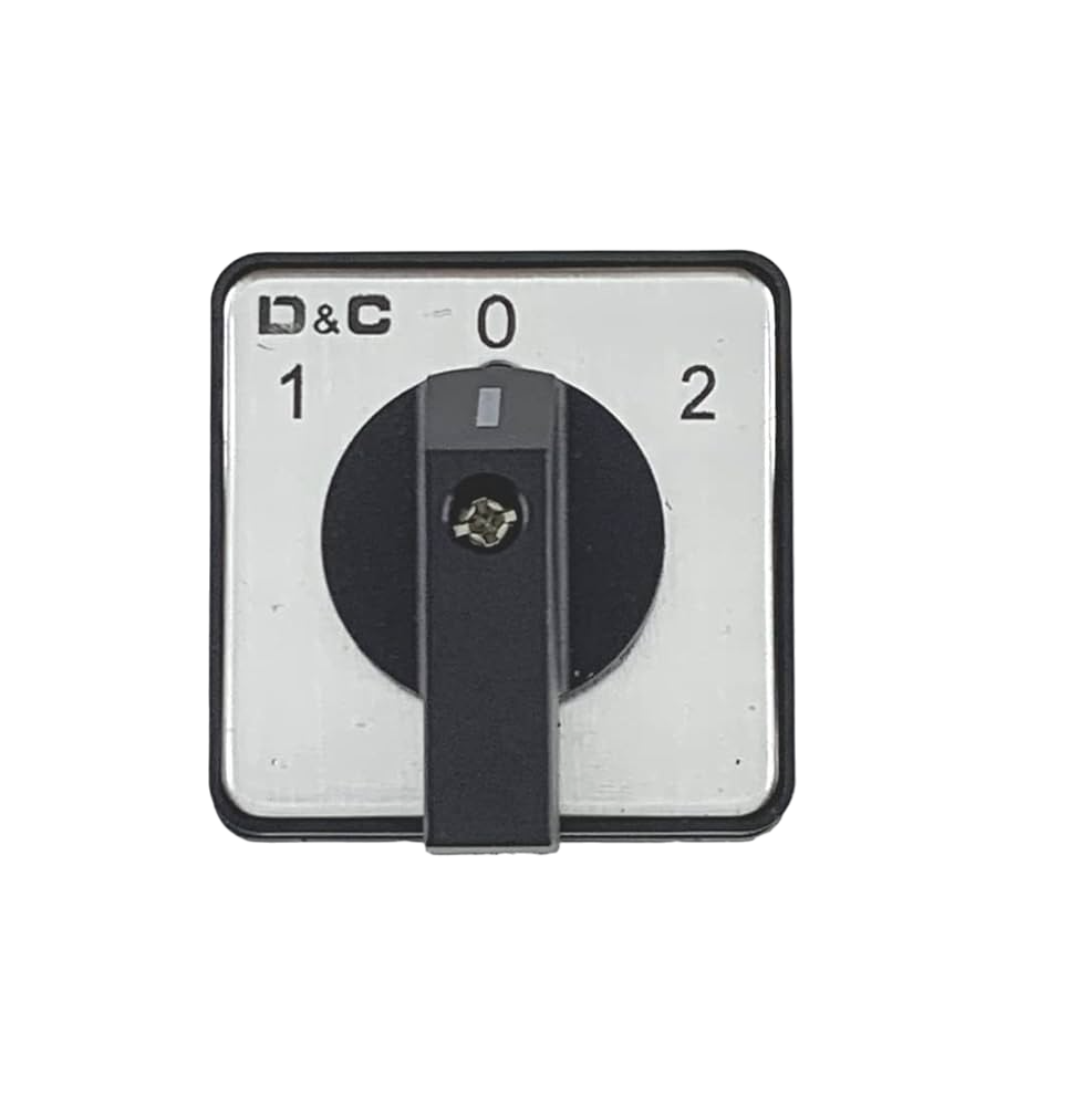
A Selector Switch 2, commonly referred to as a rotary switch, is an electromechanical component that enables the user to select between multiple options or settings. It operates by turning a knob to one of its several fixed positions, each connecting a different set of contacts within the switch. This type of switch is widely used in applications where more than two positions are required, such as selecting different modes of operation, adjusting settings, or as an input device for control panels.
Explore Projects Built with Selector Sw 2
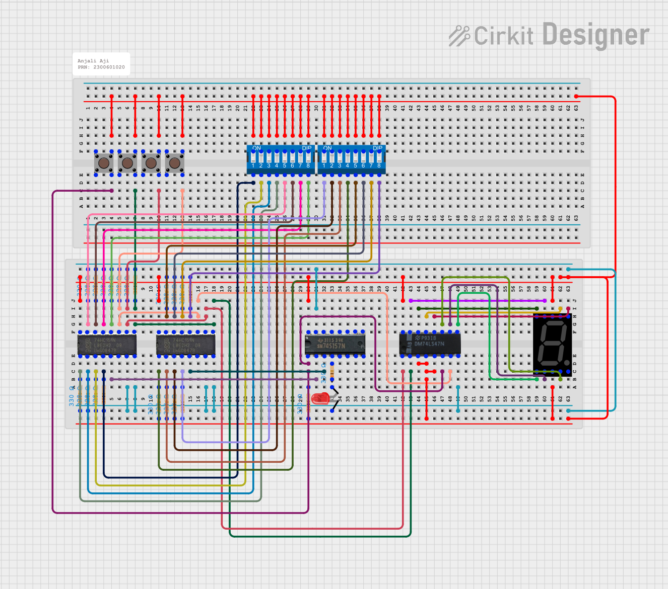
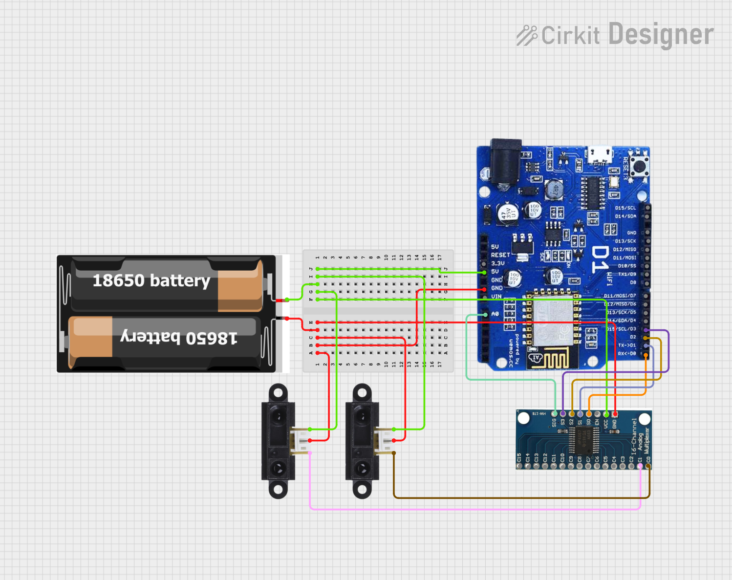

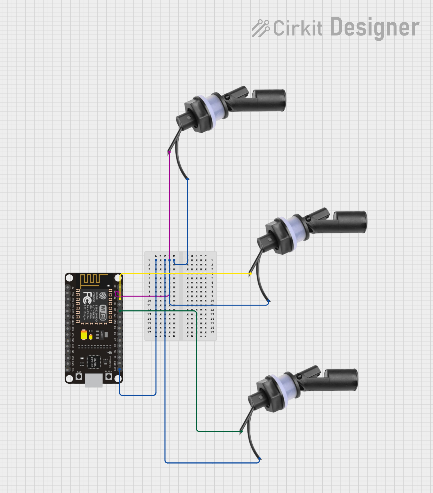
Explore Projects Built with Selector Sw 2
Common Applications and Use Cases
- Multi-speed fans or motors
- Control panels for machinery
- Mode selectors in electronic devices
- Input selectors in audio/video equipment
- Function selectors in measurement instruments
Technical Specifications
Key Technical Details
- Voltage Rating: Typically ranges from 5V to 250V, depending on the model.
- Current Rating: Commonly rated for currents from 100mA to 2A.
- Contact Resistance: Usually less than 50 milliohms.
- Insulation Resistance: Typically greater than 1000 megohms.
- Dielectric Strength: Often withstands 1000VAC for 1 minute.
- Mechanical Life: Can vary, often rated for 10,000 to 100,000 cycles.
- Operating Temperature: Ranges from -20°C to +70°C.
Pin Configuration and Descriptions
| Pin Number | Description |
|---|---|
| 1 | Common terminal (COM) |
| 2 | Output for position 1 (OUT1) |
| 3 | Output for position 2 (OUT2) |
| ... | ... |
| N | Output for position N (OUTN) |
Note: The actual number of positions and corresponding outputs will vary based on the specific model of the Selector Switch 2.
Usage Instructions
How to Use the Component in a Circuit
- Identify the Common Terminal: Locate the common terminal (COM) on the switch, which is the pivot point for the selector.
- Connect the Common Terminal: Attach the common terminal to the circuit node that will be the input or output shared by all switch positions.
- Connect Output Terminals: Connect each output terminal (OUT1, OUT2, ..., OUTN) to the respective circuit nodes that correspond to each selectable position.
- Mount the Switch: Secure the switch to the panel or PCB, ensuring that it is firmly in place to prevent any movement that could cause intermittent connections.
Important Considerations and Best Practices
- Voltage and Current Ratings: Ensure that the switch ratings are suitable for the application to prevent damage.
- Debouncing: Some mechanical switches may require debouncing, either through hardware or software, to avoid erratic behavior due to contact "bounce."
- Secure Connections: Use proper soldering techniques or secure connectors to prevent loose connections.
- Environmental Factors: Consider the operating environment, as extreme temperatures or humidity can affect switch performance.
Troubleshooting and FAQs
Common Issues Users Might Face
- Intermittent Connections: This can be caused by loose terminals or worn-out contacts.
- Switch Does Not Stay in Selected Position: The detent mechanism may be damaged or worn out.
- Inconsistent Switching: Debris or corrosion on contacts can lead to poor performance.
Solutions and Tips for Troubleshooting
- Check Connections: Ensure all terminals are securely connected and solder joints are intact.
- Clean Contacts: If accessible, clean the contacts with appropriate contact cleaner.
- Replace Switch: If the switch is mechanically worn out, it may need to be replaced.
FAQs
Q: Can I use the Selector Switch 2 with a microcontroller like an Arduino?
- A: Yes, you can connect the output terminals to digital input pins on an Arduino and read the switch position.
Q: How do I debounce the switch in software?
- A: Implement a delay or use a software library designed for debouncing inputs.
Example Code for Arduino UNO
// Define the digital pins connected to the switch outputs
const int switchPin1 = 2; // Position 1
const int switchPin2 = 3; // Position 2
// ... additional pins as needed

void setup() {
  // Set the switch pins as inputs
  pinMode(switchPin1, INPUT);
  pinMode(switchPin2, INPUT);
  // ... additional setup for other pins
}

void loop() {
  // Read the state of the switch positions
  int switchState1 = digitalRead(switchPin1);
  int switchState2 = digitalRead(switchPin2);
  // ... additional reads for other pins

  // Implement your logic based on the switch positions
  // Example: if position 1 is selected, turn on an LED
  if (switchState1 == HIGH) {
    // Turn on the LED
  } else {
    // Turn off the LED
  }

  // Add debouncing if necessary
  delay(50); // Simple software debounce
}
Note: The above code is a basic example to demonstrate reading the state of a Selector Switch 2 with an Arduino UNO. The actual implementation will vary based on the specific application and number of switch positions.