How to Use BlynkGate: Examples, Pinouts, and Specs
Introduction
The BlynkGate, manufactured by MakerLab with part ID 9016, is an innovative electronic component designed to bridge the gap between hardware devices and the Blynk mobile application. It serves as a logic gate that implements the Blynk protocol, facilitating Internet of Things (IoT) projects by enabling remote monitoring and control of sensors and other hardware devices through the Blynk platform.
Explore Projects Built with BlynkGate
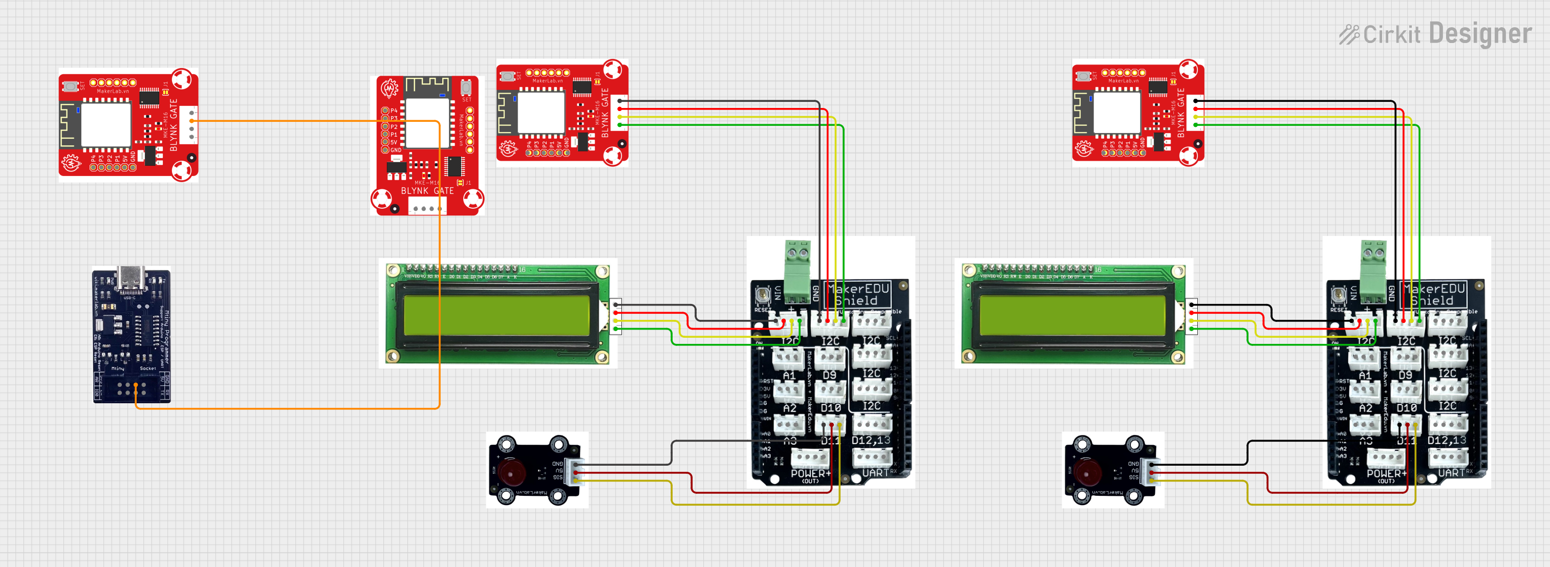
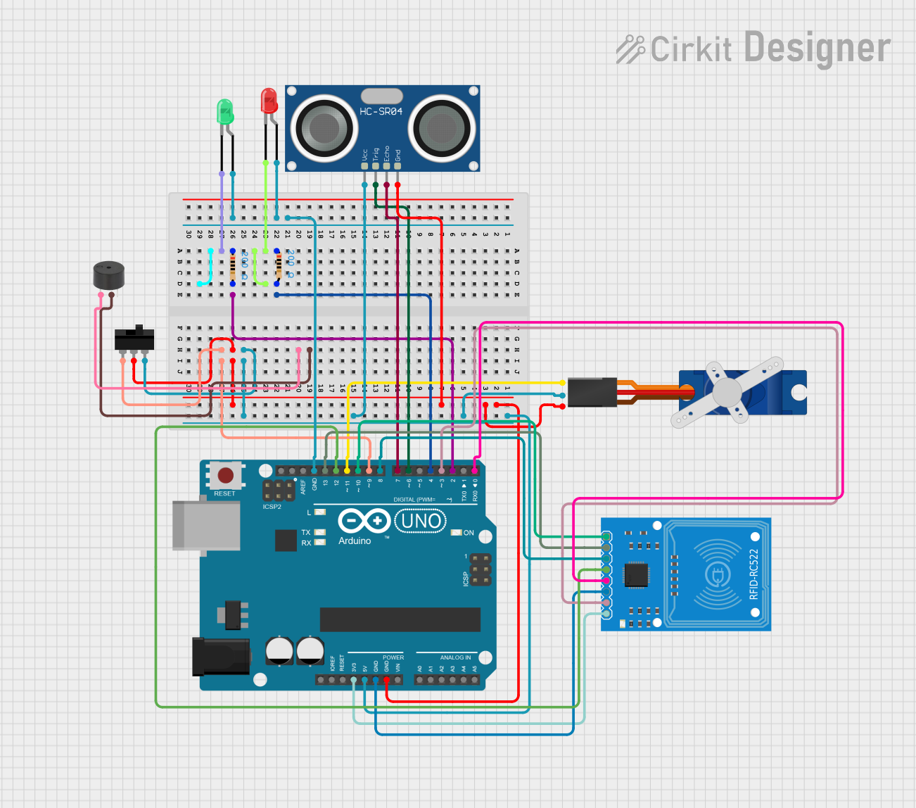
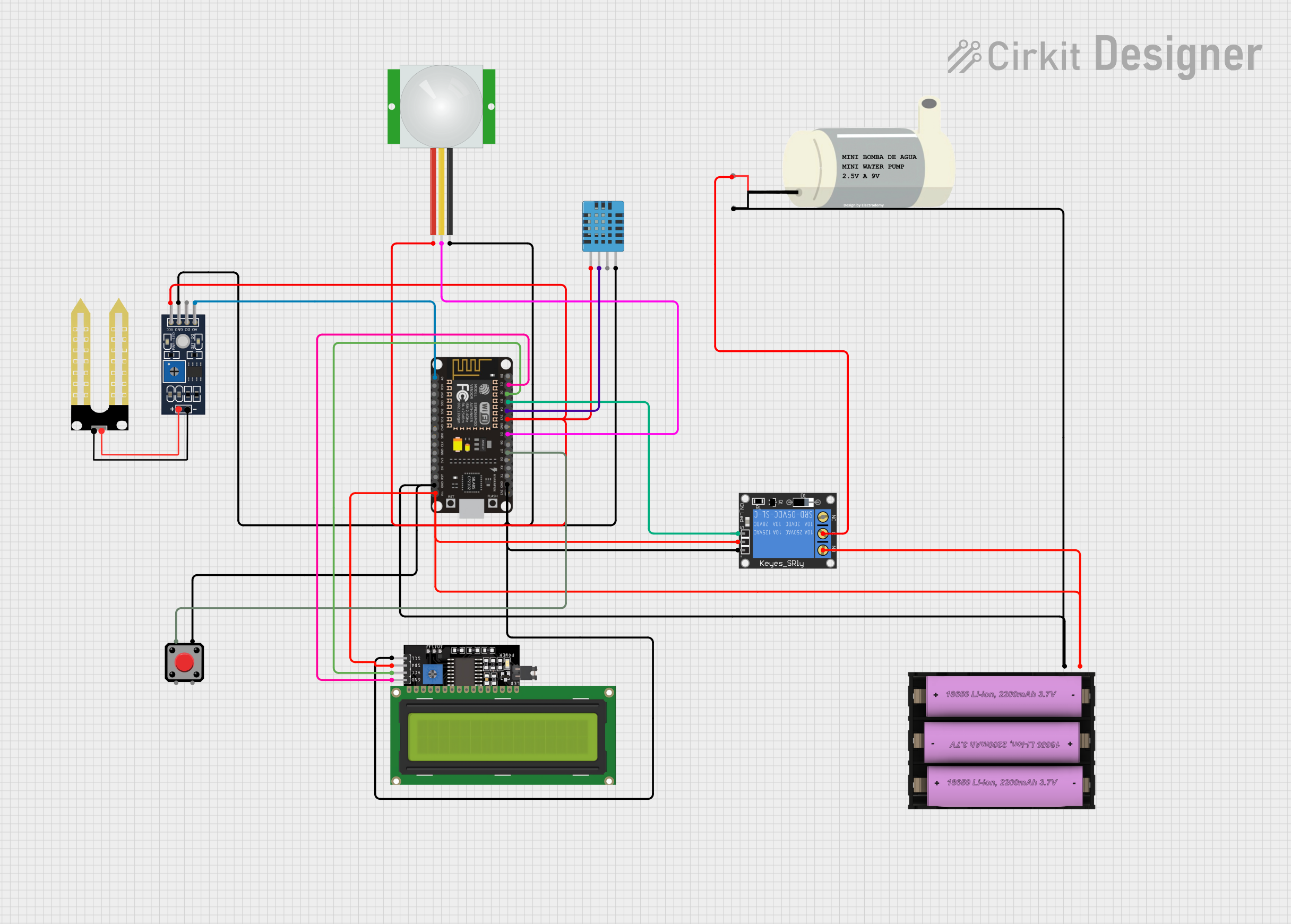

Explore Projects Built with BlynkGate
Common Applications and Use Cases
- Home automation systems
- Remote sensor monitoring
- IoT educational projects
- Smart agriculture
- DIY IoT projects
Technical Specifications
Key Technical Details
- Operating Voltage: 3.3V to 5V
- Logic Level: TTL compatible
- Communication: Wi-Fi (802.11 b/g/n)
- Supported Protocols: Blynk, HTTP, MQTT
- Dimensions: 25mm x 15mm
Pin Configuration and Descriptions
| Pin Number | Name | Description |
|---|---|---|
| 1 | VCC | Power supply (3.3V-5V) |
| 2 | GND | Ground connection |
| 3 | TX | Transmit pin for serial communication |
| 4 | RX | Receive pin for serial communication |
| 5 | RST | Reset pin (active low) |
| 6 | GPIO | General Purpose Input/Output for user-defined functions |
Usage Instructions
How to Use the BlynkGate in a Circuit
Powering the BlynkGate: Connect the VCC pin to a 3.3V or 5V power supply and the GND pin to the ground.
Serial Communication: Connect the TX and RX pins to the corresponding RX and TX pins of your microcontroller (e.g., Arduino UNO).
Reset: The RST pin can be connected to a digital pin on your microcontroller to allow software reset.
GPIO: Utilize the GPIO pin for additional hardware interfacing as required by your project.
Important Considerations and Best Practices
- Ensure that the power supply is within the specified voltage range to prevent damage.
- Use level shifters if interfacing with a microcontroller operating at a different logic level.
- Establish a stable Wi-Fi connection for reliable communication with the Blynk app.
- Update the Blynk library to the latest version for compatibility.
Example Code for Arduino UNO
#include <BlynkSimpleEsp8266.h>

// Your WiFi credentials.
// Set password to "" for open networks.
char ssid[] = "YourNetworkName";
char pass[] = "YourPassword";

// Your Blynk auth token.
char auth[] = "YourAuthToken";

void setup() {
  // Debug console
  Serial.begin(9600);

  // Set ESP8266 baud rate
  Serial1.begin(115200);
  Blynk.begin(auth, ssid, pass, Serial1);

  // You can also specify server:
  //Blynk.begin(auth, ssid, pass, Serial1, "blynk-cloud.com", 80);
}

void loop() {
  Blynk.run();
}
Note: Replace YourNetworkName, YourPassword, and YourAuthToken with your actual Wi-Fi credentials and Blynk authorization token.
Troubleshooting and FAQs
Common Issues
- Device not connecting to Wi-Fi: Ensure the SSID and password are correct and that the Wi-Fi signal is strong enough.
- BlynkGate not responding: Check the power supply and ensure the RST pin is not being held low.
- Serial communication errors: Verify that the TX and RX connections are correct and the baud rate matches the microcontroller settings.
Solutions and Tips for Troubleshooting
- Double-check wiring and connections.
- Reset the BlynkGate using the RST pin.
- Update the Blynk library to the latest version.
- Consult the Blynk community forums for additional support.
FAQs
Q: Can the BlynkGate be used with other microcontrollers besides Arduino UNO?
A: Yes, the BlynkGate is compatible with any microcontroller that supports serial communication and can connect to the Blynk platform.
Q: Is it possible to use multiple BlynkGates in a single project?
A: Yes, you can use multiple BlynkGates in a project, but each must have a unique Blynk authorization token and be managed separately within the Blynk app.
Q: How do I update the firmware on the BlynkGate?
A: Firmware updates can be done through the serial interface using the appropriate tools and firmware files provided by MakerLab. Follow the manufacturer's instructions for the update process.