How to Use Relay Module 30 A / 250 VAC: Examples, Pinouts, and Specs
Introduction
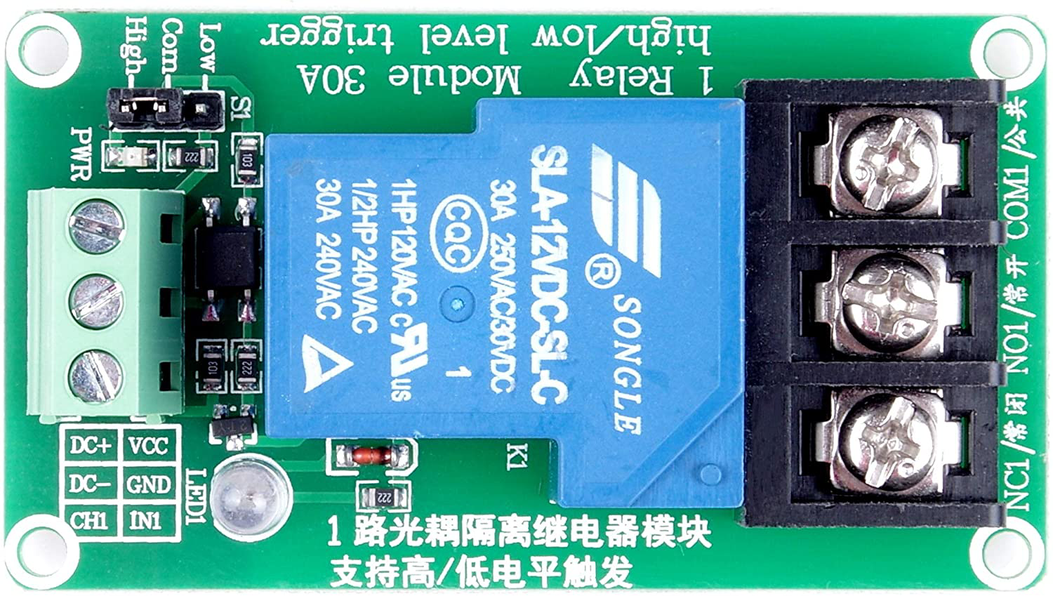
The Relay Module 30 A / 250 VAC is an electromechanical switching device designed to control high-power loads using low-power control signals. It is capable of switching loads up to 30 Amperes at 250 Volts AC, making it ideal for applications requiring the control of high-power devices such as motors, heaters, and lighting systems. The module typically includes an optocoupler for electrical isolation, ensuring safe operation when interfacing with microcontrollers or other low-voltage control systems.
Explore Projects Built with Relay Module 30 A / 250 VAC

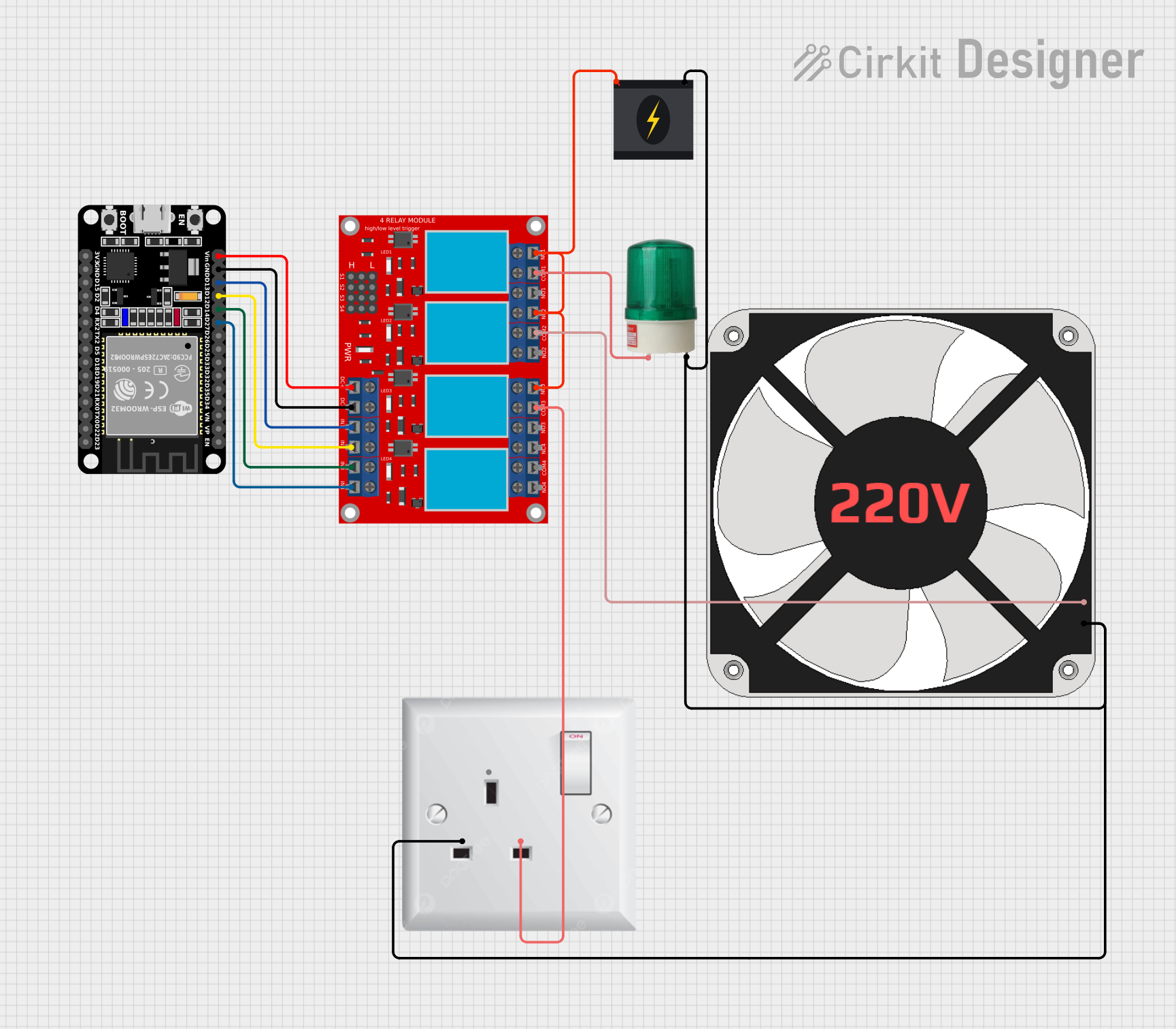
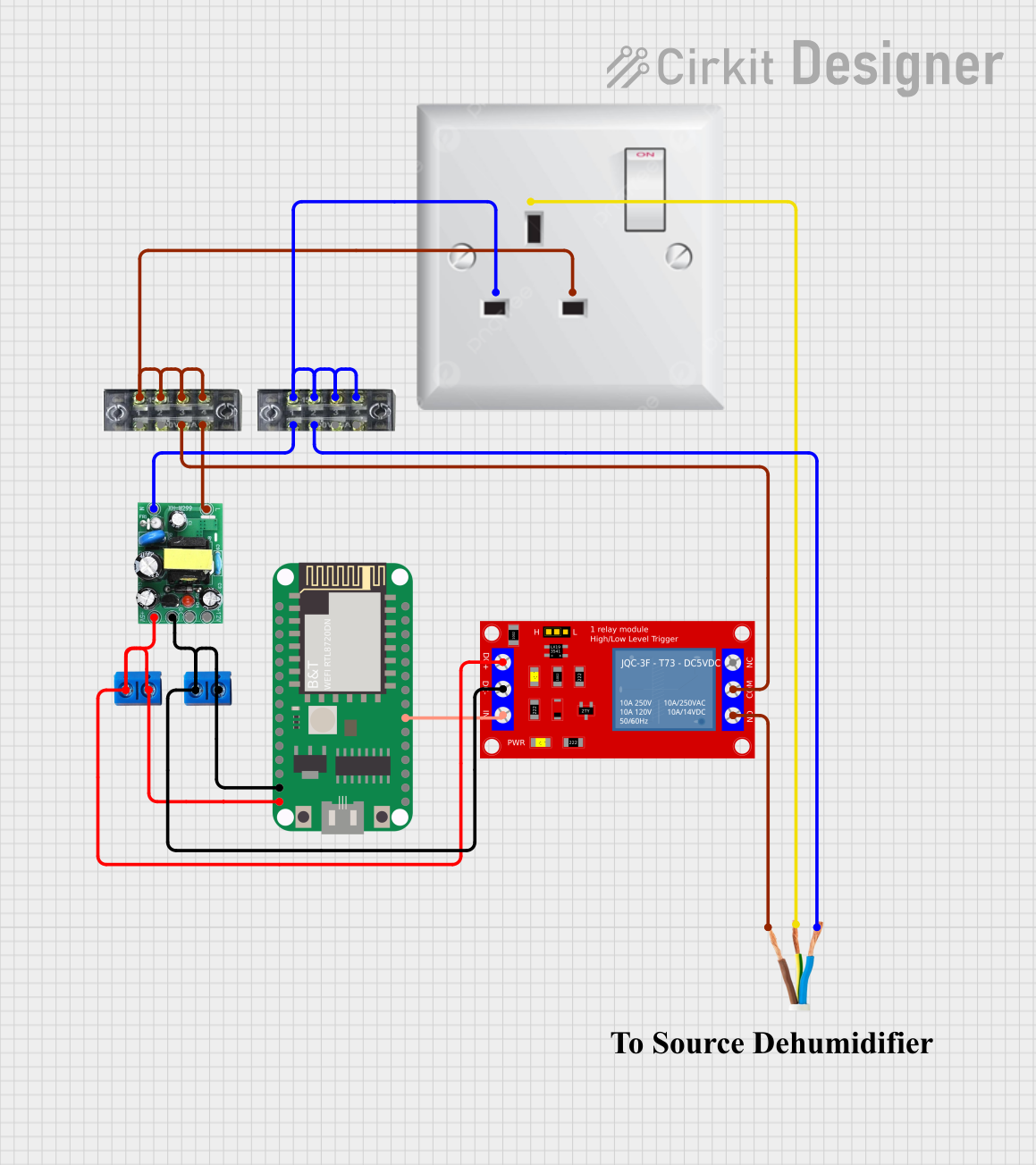
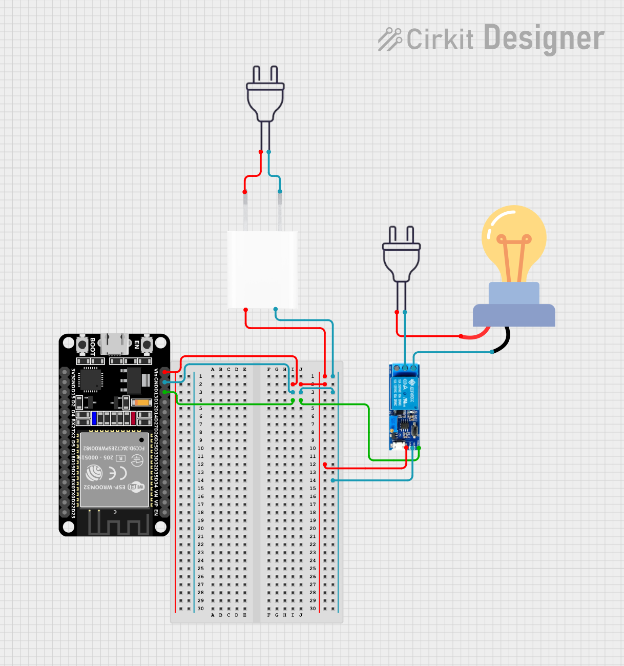
Explore Projects Built with Relay Module 30 A / 250 VAC
Common Applications and Use Cases
- Home automation systems (e.g., controlling appliances or lighting)
- Industrial equipment control
- Motor and pump control
- HVAC systems
- Smart energy management systems
Technical Specifications
Key Technical Details
- Operating Voltage (Control Side): 5V DC (typical)
- Trigger Current: 15-20 mA
- Relay Contact Ratings:
- Maximum Voltage: 250 VAC / 30 A
- Maximum Current: 30 A
- Relay Type: SPDT (Single Pole Double Throw)
- Electrical Isolation: Optocoupler-based
- Indicator LED: Onboard LED to indicate relay activation
- Dimensions: Varies by manufacturer, typically compact for easy integration
Pin Configuration and Descriptions
The relay module typically has the following pins:
Control Side (Low Voltage)
| Pin Name | Description |
|---|---|
| VCC | Connect to the 5V DC power supply. |
| GND | Connect to the ground of the power supply or microcontroller. |
| IN | Control signal input. A HIGH signal activates the relay, and a LOW signal deactivates it. |
Load Side (High Voltage)
| Terminal Name | Description |
|---|---|
| COM | Common terminal for the relay. Connect to the power source or load. |
| NO | Normally Open terminal. The circuit is open when the relay is inactive. |
| NC | Normally Closed terminal. The circuit is closed when the relay is inactive. |
Usage Instructions
How to Use the Component in a Circuit
- Power the Module:
- Connect the VCC pin to a 5V DC power supply and the GND pin to the ground.
- Control Signal:
- Connect the IN pin to a digital output pin of a microcontroller (e.g., Arduino UNO).
- When the microcontroller outputs a HIGH signal, the relay will activate, closing the NO terminal and opening the NC terminal.
- Load Connection:
- Connect the high-power load to the COM and NO terminals if you want the load to turn on when the relay is activated.
- Alternatively, connect the load to the COM and NC terminals if you want the load to turn off when the relay is activated.
Important Considerations and Best Practices
- Electrical Isolation: Ensure proper isolation between the control and load sides to prevent damage to the microcontroller.
- Flyback Diode: If controlling an inductive load (e.g., motor), use a flyback diode across the load to suppress voltage spikes.
- Heat Dissipation: Ensure adequate ventilation or heat dissipation for high-current loads to prevent overheating.
- Safety Precautions: Always handle high-voltage connections with care. Disconnect power before wiring the load side.
Example: Connecting to an Arduino UNO
Below is an example of how to control the relay module using an Arduino UNO:
// Define the pin connected to the relay module's IN pin
const int relayPin = 7;

void setup() {
  // Set the relay pin as an output
  pinMode(relayPin, OUTPUT);

  // Ensure the relay is off at startup
  digitalWrite(relayPin, LOW);
}

void loop() {
  // Turn the relay on (activate the connected load)
  digitalWrite(relayPin, HIGH);
  delay(5000); // Keep the relay on for 5 seconds

  // Turn the relay off (deactivate the connected load)
  digitalWrite(relayPin, LOW);
  delay(5000); // Keep the relay off for 5 seconds
}
Troubleshooting and FAQs
Common Issues and Solutions
Relay Not Activating:
- Cause: Insufficient control voltage or current.
- Solution: Ensure the control signal is 5V and the source can supply at least 15-20 mA.
Load Not Switching:
- Cause: Incorrect wiring on the load side.
- Solution: Verify the connections to the COM, NO, and NC terminals.
Microcontroller Resetting:
- Cause: Voltage spikes from the relay coil or load.
- Solution: Use a flyback diode across the relay coil and/or load.
Relay Stuck in One State:
- Cause: Relay contacts may be damaged due to overcurrent.
- Solution: Ensure the load does not exceed the relay's 30 A / 250 VAC rating.
FAQs
Q: Can I use this relay module with a 3.3V microcontroller?
A: Most relay modules require a 5V control signal. If using a 3.3V microcontroller, you may need a level shifter or a transistor to boost the control signal to 5V.
Q: Is it safe to use this relay module for DC loads?
A: Yes, but ensure the DC load does not exceed the relay's current and voltage ratings. Note that DC loads may cause faster wear on the relay contacts.
Q: Can I control multiple relays with one microcontroller?
A: Yes, as long as the microcontroller has enough GPIO pins and can supply the required current for each relay's control circuit.