How to Use 4 channel relay module: Examples, Pinouts, and Specs
Introduction
A 4 channel relay module is an electronic device designed to control up to four high-power electrical loads using low-power control signals. This module is an essential component in various applications such as home automation systems, robotics, and industrial control systems. It acts as an electrically operated switch, which can be controlled by a microcontroller like an Arduino UNO.
Explore Projects Built with 4 channel relay module


Explore Projects Built with 4 channel relay module
Common Applications and Use Cases
- Home automation (e.g., controlling lights, fans, and other household appliances)
- Robotics (e.g., controlling motors, actuators)
- Industrial controls (e.g., turning on/off machinery, process control)
- Remote control systems
Technical Specifications
Key Technical Details
- Operating Voltage (VCC): 5V DC
- Trigger Voltage (IN1-IN4): 0-5V DC
- Max Switching Voltage: 250V AC / 30V DC
- Max Switching Current: 10A per channel
- Relay Life: 100,000 cycles (typical)
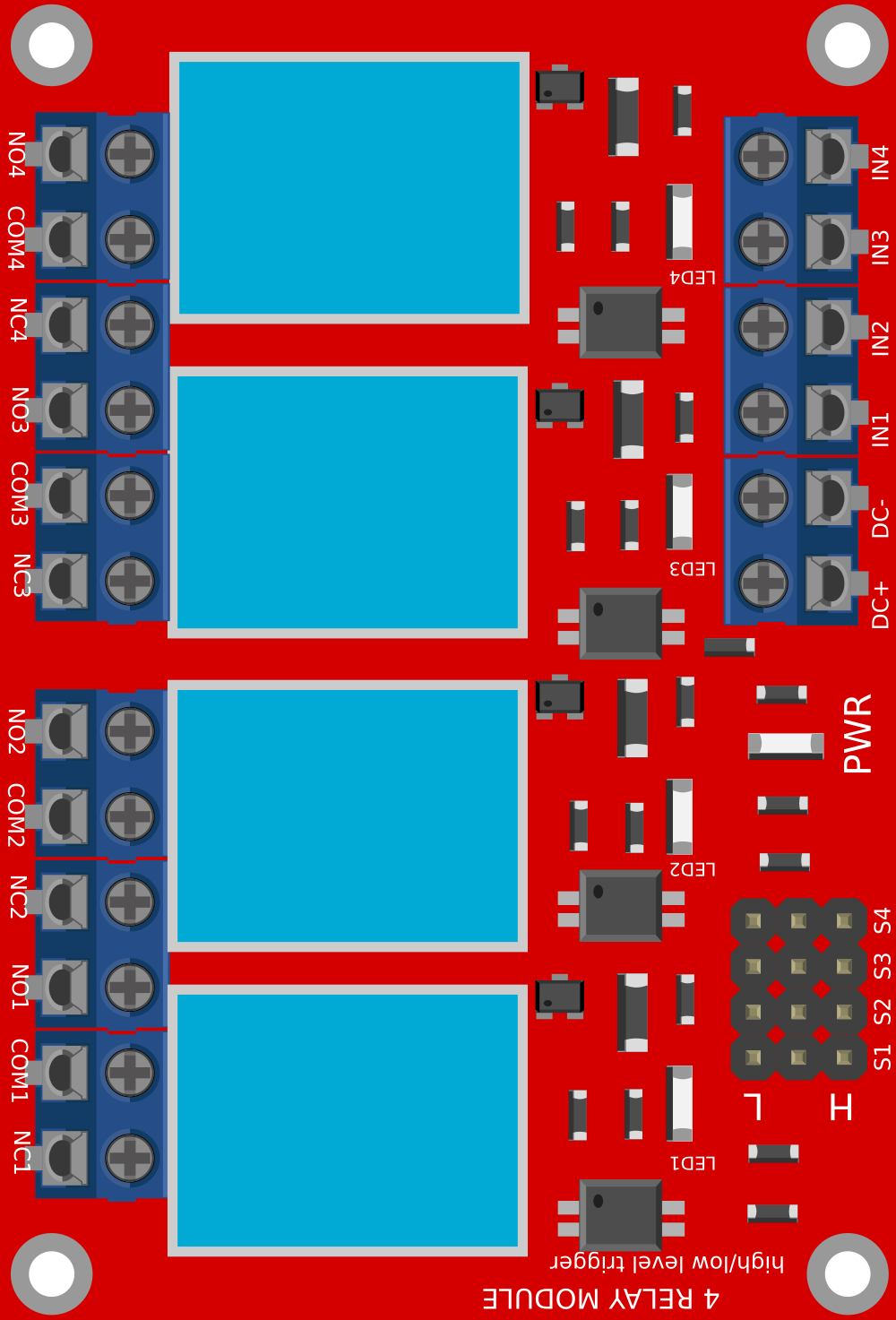
Pin Configuration and Descriptions
| Pin Name | Description |
|---|---|
| VCC | Connect to 5V power supply |
| GND | Connect to ground |
| IN1 | Control signal for Relay 1 (active LOW/HIGH) |
| IN2 | Control signal for Relay 2 (active LOW/HIGH) |
| IN3 | Control signal for Relay 3 (active LOW/HIGH) |
| IN4 | Control signal for Relay 4 (active LOW/HIGH) |
| NO1-NO4 | Normally Open contact for Relays 1-4 |
| NC1-NC4 | Normally Closed contact for Relays 1-4 |
| COM1-COM4 | Common contact for Relays 1-4 |
Usage Instructions
How to Use the Component in a Circuit
Powering the Module:
- Connect the VCC pin to a 5V power supply.
- Connect the GND pin to the ground of the power supply.
Connecting Control Signals:
- Connect IN1 to IN4 pins to the digital outputs of a microcontroller (e.g., Arduino UNO).
Connecting Loads:
- Connect the device you want to control to the NO (Normally Open) or NC (Normally Closed) and COM (Common) pins of the relay.
Important Considerations and Best Practices
- Ensure the power supply can deliver sufficient current for all relays to operate simultaneously if needed.
- Do not exceed the maximum voltage and current ratings of the relays.
- Use flyback diodes across inductive loads to prevent back EMF damage.
- Consider using opto-isolation between the control circuit and the relay module to protect the microcontroller from voltage spikes.
Example Code for Arduino UNO
// Define relay control pins
const int relay1 = 2;
const int relay2 = 3;
const int relay3 = 4;
const int relay4 = 5;

void setup() {
  // Set relay pins as outputs
  pinMode(relay1, OUTPUT);
  pinMode(relay2, OUTPUT);
  pinMode(relay3, OUTPUT);
  pinMode(relay4, OUTPUT);
}

void loop() {
  // Turn on all relays
  digitalWrite(relay1, HIGH);
  digitalWrite(relay2, HIGH);
  digitalWrite(relay3, HIGH);
  digitalWrite(relay4, HIGH);
  delay(1000); // Wait for 1 second

  // Turn off all relays
  digitalWrite(relay1, LOW);
  digitalWrite(relay2, LOW);
  digitalWrite(relay3, LOW);
  digitalWrite(relay4, LOW);
  delay(1000); // Wait for 1 second
}
Troubleshooting and FAQs
Common Issues
- Relay not activating: Check the control signal voltage and connections.
- Intermittent operation: Verify power supply stability and relay wiring.
- Noise issues: Use snubber circuits or flyback diodes for inductive loads.
Solutions and Tips for Troubleshooting
- Ensure that the input signal is within the specified range (0-5V DC).
- Check for loose connections or soldering issues on the relay module.
- If using inductive loads, make sure flyback diodes are installed correctly.
- Test each relay independently to isolate the issue.
FAQs
Q: Can I control the relay module with a 3.3V signal? A: Some relay modules can be triggered with 3.3V, but it's essential to check the specific module's requirements.
Q: Is it safe to control AC mains with this relay module? A: Yes, but it should be done by a qualified electrician and with proper safety measures in place.
Q: Can I use PWM to control the relay? A: Relays are not designed for PWM control and should only be used for on/off control.
Q: How do I know if the relay is in NO or NC mode? A: The relay is in NO mode when the control signal is HIGH (or LOW if designed as active LOW), and in NC mode when the control signal is not applied.