Cirkit Designer Logo
Cirkit Designer
Your all-in-one circuit design IDE
Home / 
Component Documentation

How to Use RS 232: Examples, Pinouts, and Specs

Image of RS 232
Cirkit Designer LogoDesign with RS 232 in Cirkit Designer

Introduction

RS-232 is a widely used standard for serial communication that defines the electrical characteristics, signal timing, and physical interface for data exchange. It is primarily used to connect computers to peripherals such as modems, printers, and industrial equipment. RS-232 enables point-to-point communication and is known for its simplicity and reliability in low-speed data transmission.

Explore Projects Built with RS 232

Use Cirkit Designer to design, explore, and prototype these projects online. Some projects support real-time simulation. Click "Open Project" to start designing instantly!
Arduino UNO RS232 Serial Communication Interface
Image of Reddit Help - RS232 Serial Communication With Digital Scale: A project utilizing RS 232 in a practical application
This circuit connects an Arduino UNO to an RS232 to Serial Converter, allowing the Arduino to communicate with RS232-compatible devices. The Arduino's digital pins D10 and D11 are used for RX and TX communication, respectively, and are interfaced with the corresponding TX and RX pins of the RS232 converter. The embedded code on the Arduino sets up a software serial port for communication with the RS232 converter and relays data between the standard serial port and the software serial port.
Cirkit Designer LogoOpen Project in Cirkit Designer
Arduino UNO and Relay-Controlled RS485 Communication System
Image of Diagrama: A project utilizing RS 232 in a practical application
This circuit features an Arduino UNO microcontroller interfaced with a 4-channel relay module and a UART TTL to RS485 converter. The Arduino controls the relays via digital pins and communicates with the RS485 converter for serial communication, enabling control of external devices and communication over long distances.
Cirkit Designer LogoOpen Project in Cirkit Designer
Satellite-Based Timing and Navigation System with SDR and Atomic Clock Synchronization
Image of GPS 시스템 측정 구성도_Confirm: A project utilizing RS 232 in a practical application
This circuit appears to be a complex system involving power supply management, GPS and timing synchronization, and data communication. It includes a SI-TEX G1 Satellite Compass for GPS data, an XHTF1021 Atomic Rubidium Clock for precise timing, and Ettus USRP B200 units for software-defined radio communication. Power is supplied through various SMPS units and distributed via terminal blocks and DC jacks. Data communication is facilitated by Beelink MINI S12 N95 computers, RS232 splitters, and a 1000BASE-T Media Converter for network connectivity. RF Directional Couplers are used to interface antennas with the USRP units, and the entire system is likely contained within cases for protection and organization.
Cirkit Designer LogoOpen Project in Cirkit Designer
Satellite Compass and Network-Integrated GPS Data Processing System
Image of GPS 시스템 측정 구성도_241016: A project utilizing RS 232 in a practical application
This circuit comprises a satellite compass, a mini PC, two GPS antennas, power supplies, a network switch, media converters, and an atomic rubidium clock. The satellite compass is powered by a triple output DC power supply and interfaces with an RS232 splitter for 1PPS signals. The mini PCs are connected to the USRP B200 devices via USB for data and power, and to media converters via Ethernet, which in turn connect to a network switch using fiber optic links. The antennas are connected to the USRP B200s through RF directional couplers, and the atomic clock provides a 1PPS input to the RS232 splitter.
Cirkit Designer LogoOpen Project in Cirkit Designer

Explore Projects Built with RS 232

Use Cirkit Designer to design, explore, and prototype these projects online. Some projects support real-time simulation. Click "Open Project" to start designing instantly!
Image of Reddit Help - RS232 Serial Communication With Digital Scale: A project utilizing RS 232 in a practical application
Arduino UNO RS232 Serial Communication Interface
This circuit connects an Arduino UNO to an RS232 to Serial Converter, allowing the Arduino to communicate with RS232-compatible devices. The Arduino's digital pins D10 and D11 are used for RX and TX communication, respectively, and are interfaced with the corresponding TX and RX pins of the RS232 converter. The embedded code on the Arduino sets up a software serial port for communication with the RS232 converter and relays data between the standard serial port and the software serial port.
Cirkit Designer LogoOpen Project in Cirkit Designer
Image of Diagrama: A project utilizing RS 232 in a practical application
Arduino UNO and Relay-Controlled RS485 Communication System
This circuit features an Arduino UNO microcontroller interfaced with a 4-channel relay module and a UART TTL to RS485 converter. The Arduino controls the relays via digital pins and communicates with the RS485 converter for serial communication, enabling control of external devices and communication over long distances.
Cirkit Designer LogoOpen Project in Cirkit Designer
Image of GPS 시스템 측정 구성도_Confirm: A project utilizing RS 232 in a practical application
Satellite-Based Timing and Navigation System with SDR and Atomic Clock Synchronization
This circuit appears to be a complex system involving power supply management, GPS and timing synchronization, and data communication. It includes a SI-TEX G1 Satellite Compass for GPS data, an XHTF1021 Atomic Rubidium Clock for precise timing, and Ettus USRP B200 units for software-defined radio communication. Power is supplied through various SMPS units and distributed via terminal blocks and DC jacks. Data communication is facilitated by Beelink MINI S12 N95 computers, RS232 splitters, and a 1000BASE-T Media Converter for network connectivity. RF Directional Couplers are used to interface antennas with the USRP units, and the entire system is likely contained within cases for protection and organization.
Cirkit Designer LogoOpen Project in Cirkit Designer
Image of GPS 시스템 측정 구성도_241016: A project utilizing RS 232 in a practical application
Satellite Compass and Network-Integrated GPS Data Processing System
This circuit comprises a satellite compass, a mini PC, two GPS antennas, power supplies, a network switch, media converters, and an atomic rubidium clock. The satellite compass is powered by a triple output DC power supply and interfaces with an RS232 splitter for 1PPS signals. The mini PCs are connected to the USRP B200 devices via USB for data and power, and to media converters via Ethernet, which in turn connect to a network switch using fiber optic links. The antennas are connected to the USRP B200s through RF directional couplers, and the atomic clock provides a 1PPS input to the RS232 splitter.
Cirkit Designer LogoOpen Project in Cirkit Designer

Common Applications and Use Cases

  • Connecting computers to modems for data transfer
  • Industrial automation and control systems
  • Serial communication with microcontrollers and embedded systems
  • Debugging and programming devices
  • Communication with legacy hardware

Technical Specifications

Key Technical Details

  • Voltage Levels: ±3V to ±15V (typical ±12V for data signals)
  • Baud Rate: Up to 115,200 bits per second (bps) (varies by implementation)
  • Signal Type: Unbalanced (single-ended)
  • Maximum Cable Length: 15 meters (50 feet) at 19,200 bps (longer distances possible at lower speeds)
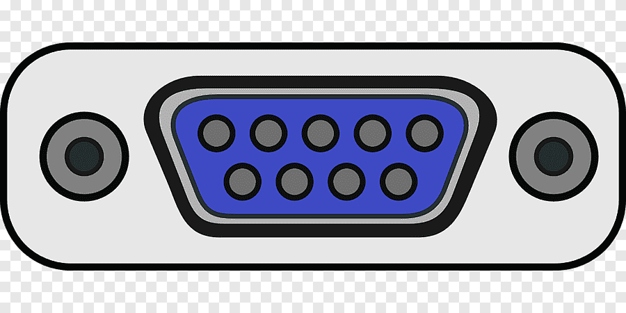
  • Connector Types: DB9 (9-pin) and DB25 (25-pin) are the most common
  • Communication Mode: Full-duplex (simultaneous bidirectional communication)

Pin Configuration and Descriptions

DB9 Connector Pinout

Pin Number Name Direction Description
1 DCD (Data Carrier Detect) Input Indicates the presence of a carrier signal from the modem.
2 RXD (Receive Data) Input Data received by the device.
3 TXD (Transmit Data) Output Data transmitted by the device.
4 DTR (Data Terminal Ready) Output Indicates the device is ready to communicate.
5 GND (Ground) - Signal ground.
6 DSR (Data Set Ready) Input Indicates the modem is ready to communicate.
7 RTS (Request to Send) Output Indicates the device is ready to send data.
8 CTS (Clear to Send) Input Indicates the modem is ready to receive data.
9 RI (Ring Indicator) Input Indicates an incoming call (used in modems).

DB25 Connector Pinout (Subset)

Pin Number Name Direction Description
2 TXD (Transmit Data) Output Data transmitted by the device.
3 RXD (Receive Data) Input Data received by the device.
4 RTS (Request to Send) Output Indicates the device is ready to send data.
5 CTS (Clear to Send) Input Indicates the modem is ready to receive data.
7 GND (Ground) - Signal ground.

Usage Instructions

How to Use RS-232 in a Circuit

  1. Connect the RS-232 Device: Use a DB9 or DB25 cable to connect the RS-232 device to the host (e.g., computer or microcontroller).
  2. Match Voltage Levels: Ensure the RS-232 voltage levels are compatible with the connected device. If interfacing with a microcontroller, use a level shifter (e.g., MAX232) to convert RS-232 signals to TTL levels.
  3. Configure Communication Parameters: Set the baud rate, parity, data bits, and stop bits to match the settings of the connected device.
  4. Establish Communication: Use appropriate software or firmware to send and receive data over the RS-232 interface.

Important Considerations and Best Practices

  • Cable Length: Keep the cable length within the standard limit to avoid signal degradation.
  • Grounding: Ensure proper grounding to prevent noise and communication errors.
  • Signal Integrity: Use shielded cables in noisy environments to maintain signal quality.
  • Level Shifting: When interfacing with microcontrollers, use an RS-232 to TTL converter (e.g., MAX232 IC).

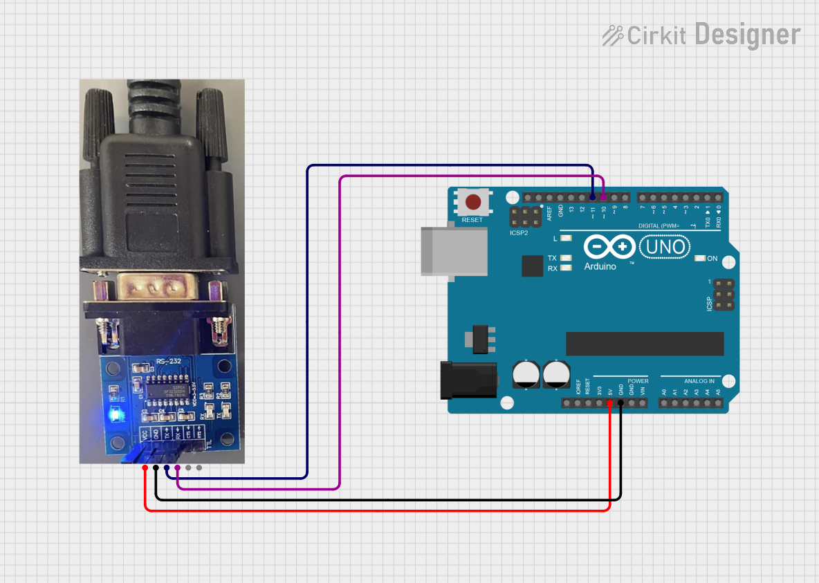
Example: Connecting RS-232 to Arduino UNO

To connect an RS-232 device to an Arduino UNO, use a MAX232 IC to convert RS-232 signals to TTL levels. Below is an example Arduino sketch for basic serial communication:

// Example: RS-232 Communication with Arduino UNO
// This code reads data from the RS-232 device and sends it to the Serial Monitor.

void setup() {
  Serial.begin(9600); // Initialize Arduino's serial communication at 9600 bps
  Serial1.begin(9600); // Initialize RS-232 communication via Serial1 (if using a board
                       // with multiple UARTs, e.g., Arduino Mega)
}

void loop() {
  // Check if data is available from the RS-232 device
  if (Serial1.available()) {
    char receivedChar = Serial1.read(); // Read a character from RS-232
    Serial.print("Received: ");         // Print the received character to Serial Monitor
    Serial.println(receivedChar);
  }

  // Check if data is available from the Serial Monitor
  if (Serial.available()) {
    char sendChar = Serial.read();      // Read a character from Serial Monitor
    Serial1.write(sendChar);           // Send the character to the RS-232 device
  }
}

Note: If using an Arduino UNO, you will need a software serial library (e.g., SoftwareSerial) since the UNO has only one hardware UART.

Troubleshooting and FAQs

Common Issues and Solutions

  1. No Communication Between Devices

    • Cause: Mismatched baud rate or communication settings.
    • Solution: Verify and match the baud rate, parity, data bits, and stop bits on both devices.
  2. Data Corruption or Noise

    • Cause: Long cable length or noisy environment.
    • Solution: Use shorter, shielded cables and ensure proper grounding.
  3. RS-232 Device Not Detected

    • Cause: Incorrect wiring or faulty cable.
    • Solution: Double-check the pin connections and test with a known working cable.
  4. Voltage Level Mismatch

    • Cause: Direct connection of RS-232 to TTL-level devices.
    • Solution: Use a level shifter (e.g., MAX232) to convert voltage levels.

FAQs

  • Q: Can RS-232 be used for multi-device communication?
    A: No, RS-232 is designed for point-to-point communication between two devices.

  • Q: What is the maximum data rate for RS-232?
    A: The standard supports up to 115,200 bps, but actual performance depends on the implementation and cable quality.

  • Q: Can I use RS-232 with modern computers?
    A: Many modern computers lack RS-232 ports, but USB-to-RS-232 adapters are widely available.

  • Q: How do I test an RS-232 connection?
    A: Use a loopback test by connecting TXD to RXD and sending data to verify the connection.