How to Use SSD1306: Examples, Pinouts, and Specs
Introduction
The SSD1306 is a monochrome OLED display driver designed to control OLED displays with resolutions up to 128x64 pixels. Manufactured by Arduino with the part ID "Uno," this versatile component supports both I2C and SPI communication protocols, making it ideal for integration into a wide range of embedded systems. Its compact size, low power consumption, and high contrast make it a popular choice for displaying text, graphics, and animations in projects such as IoT devices, wearables, and DIY electronics.
Explore Projects Built with SSD1306
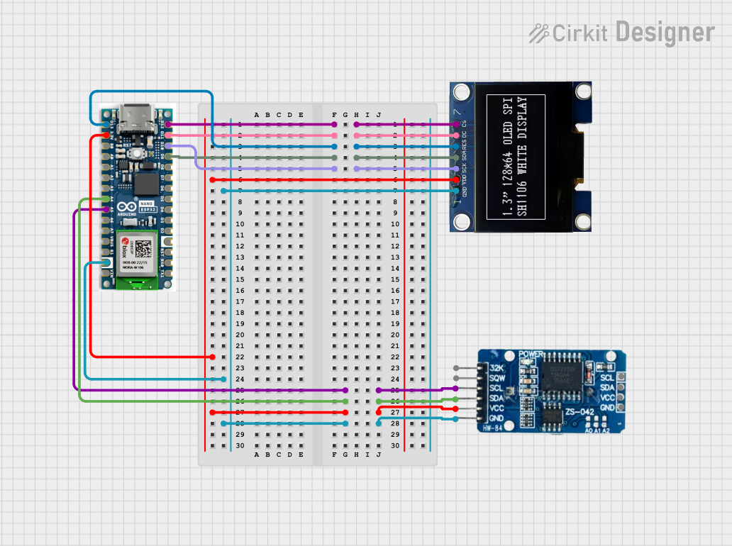
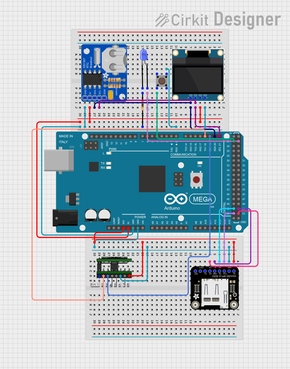

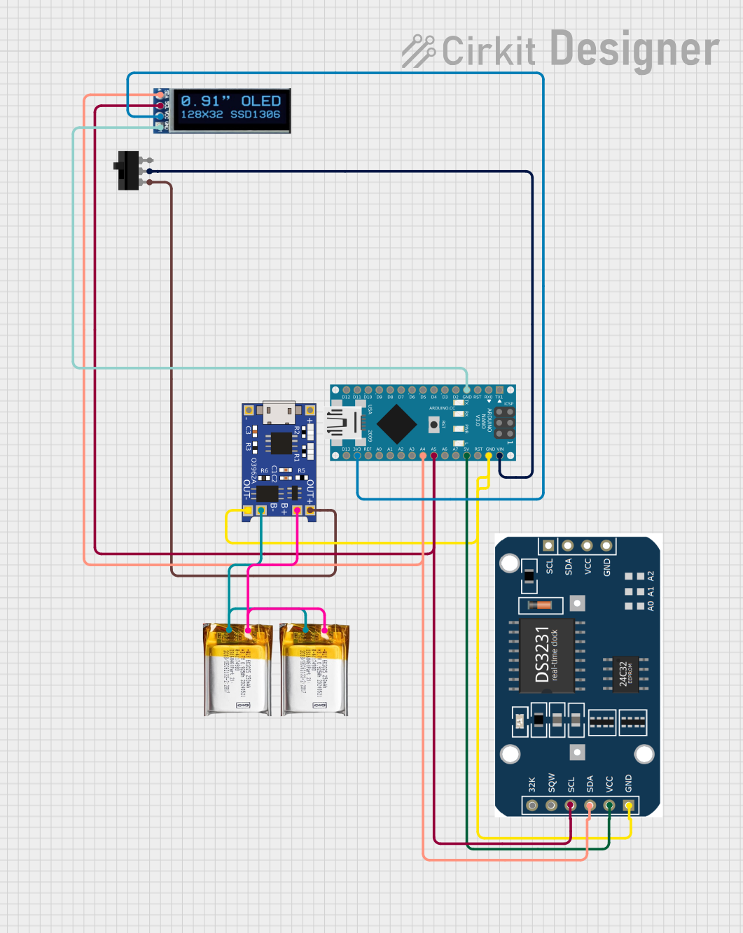
Explore Projects Built with SSD1306
Common Applications
- IoT devices for displaying sensor data
- Wearable electronics
- Portable gaming devices
- DIY projects and prototyping
- Industrial control panels
Technical Specifications
The SSD1306 OLED display driver has the following key specifications:
| Parameter | Value |
|---|---|
| Resolution | 128x64 pixels |
| Communication Protocol | I2C or SPI |
| Operating Voltage | 3.3V to 5V |
| Current Consumption | ~20mA (varies with brightness) |
| Display Type | Monochrome OLED |
| Pixel Color | White (or Blue, depending on model) |
| Operating Temperature | -40°C to +85°C |
Pin Configuration (I2C Mode)
The SSD1306 module typically has the following pinout when used in I2C mode:
| Pin Name | Description |
|---|---|
| VCC | Power supply (3.3V or 5V) |
| GND | Ground |
| SCL | Serial Clock Line (I2C) |
| SDA | Serial Data Line (I2C) |
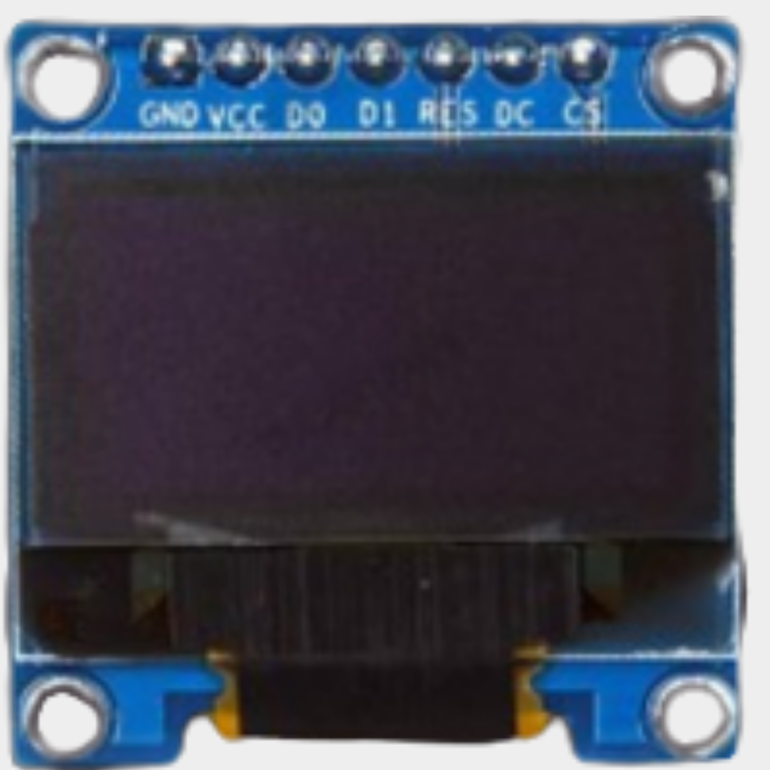
Pin Configuration (SPI Mode)
For SPI communication, the pinout is as follows:
| Pin Name | Description |
|---|---|
| VCC | Power supply (3.3V or 5V) |
| GND | Ground |
| SCK | Serial Clock Line (SPI) |
| MOSI | Master Out Slave In (SPI Data Line) |
| CS | Chip Select |
| DC | Data/Command Control |
| RES | Reset |
Usage Instructions
Connecting the SSD1306 to an Arduino UNO (I2C Mode)
Wiring: Connect the SSD1306 module to the Arduino UNO as follows:
- VCC → 5V
- GND → GND
- SCL → A5 (Arduino I2C Clock)
- SDA → A4 (Arduino I2C Data)
Install Required Libraries:
- Open the Arduino IDE.
- Go to Sketch > Include Library > Manage Libraries.
- Search for and install the following libraries:
Adafruit GFX LibraryAdafruit SSD1306
Upload Example Code: Use the following example code to display "Hello, World!" on the SSD1306:
// Include the necessary libraries
#include <Wire.h>
#include <Adafruit_GFX.h>
#include <Adafruit_SSD1306.h>

// Define the OLED display width and height
#define SCREEN_WIDTH 128
#define SCREEN_HEIGHT 64

// Create an SSD1306 display object connected via I2C
Adafruit_SSD1306 display(SCREEN_WIDTH, SCREEN_HEIGHT, &Wire, -1);

void setup() {
  // Initialize the display
  if (!display.begin(SSD1306_I2C_ADDRESS, 0x3C)) {
    // If initialization fails, print an error message
    Serial.println(F("SSD1306 allocation failed"));
    for (;;); // Halt execution
  }

  // Clear the display buffer
  display.clearDisplay();

  // Set text size and color
  display.setTextSize(1); // Text size multiplier
  display.setTextColor(SSD1306_WHITE);

  // Set cursor position
  display.setCursor(0, 0);

  // Print "Hello, World!" to the display buffer
  display.println(F("Hello, World!"));

  // Display the buffer contents on the screen
  display.display();
}

void loop() {
  // Nothing to do here
}
Important Considerations
- Power Supply: Ensure the SSD1306 module is powered within its operating voltage range (3.3V to 5V).
- Pull-Up Resistors: For I2C communication, ensure pull-up resistors (typically 4.7kΩ) are present on the SCL and SDA lines.
- Address Configuration: The default I2C address is
0x3C. If your module uses a different address, update the code accordingly. - Contrast Adjustment: Use the
display.setContrast()function to adjust the brightness of the display.
Troubleshooting and FAQs
Common Issues
Display Not Turning On:
- Verify the wiring connections.
- Ensure the power supply voltage matches the module's requirements.
- Check if the I2C address in the code matches the module's address.
Flickering or Artifacts on the Screen:
- Ensure proper grounding between the Arduino and the SSD1306 module.
- Check for loose or faulty connections.
Library Errors During Compilation:
- Ensure the
Adafruit GFX LibraryandAdafruit SSD1306libraries are installed and up to date.
- Ensure the
Blank Screen After Uploading Code:
- Confirm the I2C address (
0x3Cor0x3D) matches your module's configuration. - Verify that the
display.begin()function is called in thesetup()function.
- Confirm the I2C address (
FAQs
Q: Can the SSD1306 display graphics?
A: Yes, the SSD1306 supports graphics. You can use the Adafruit GFX Library to draw shapes, images, and animations.
Q: How do I switch between I2C and SPI modes?
A: The communication mode is determined by the module's hardware configuration. Refer to your module's datasheet or solder jumpers to switch modes.
Q: Can I use the SSD1306 with a 3.3V microcontroller?
A: Yes, the SSD1306 is compatible with both 3.3V and 5V logic levels.
Q: What is the maximum refresh rate of the SSD1306?
A: The refresh rate depends on the communication speed and the amount of data being updated. Typically, it can achieve up to 60Hz for full-screen updates.