
How to Use Arduino UNO Q: Examples, Pinouts, and Specs
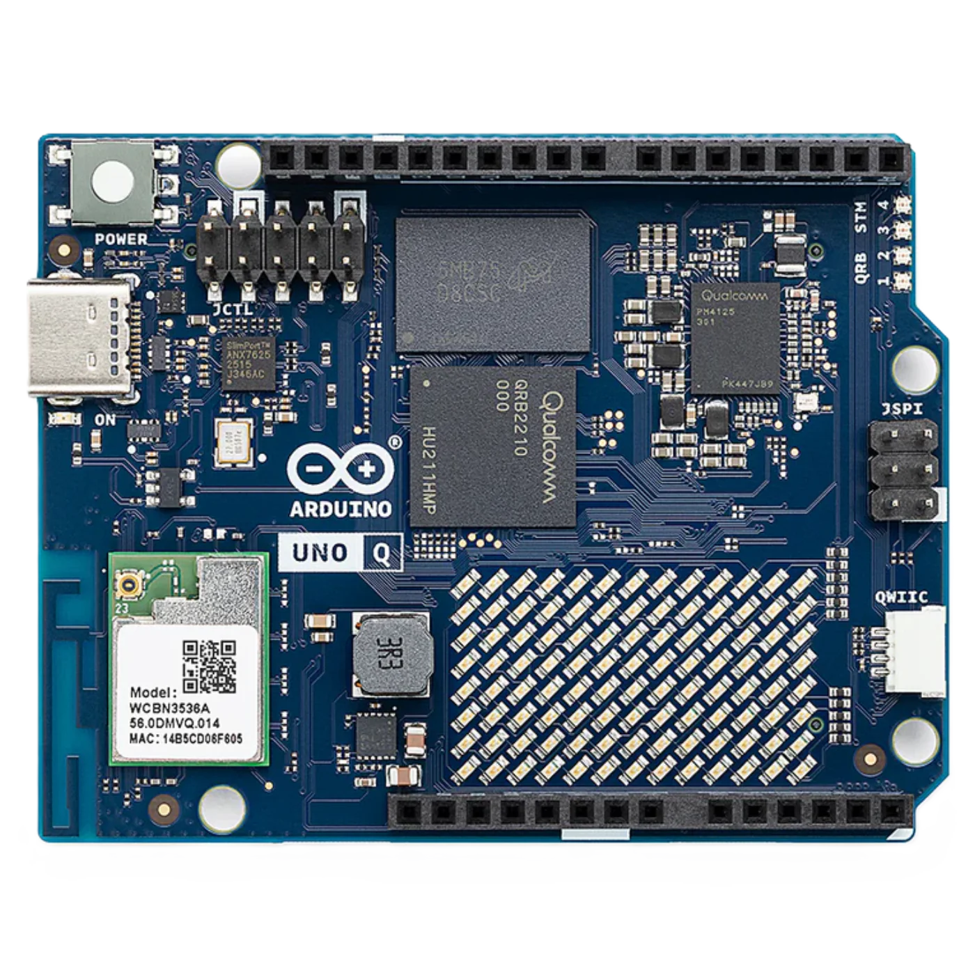
 Design with Arduino UNO Q in Cirkit Designer
Introduction
The Arduino UNO Q is a microcontroller board developed by Arduino, based on the ATmega328P microcontroller. It features 14 digital input/output pins (6 of which can be used as PWM outputs), 6 analog inputs, a USB connection for programming, and a power jack for external power supply. The board is designed to be user-friendly, making it an excellent choice for beginners and professionals alike. It is widely used in interactive projects, prototyping, and educational environments.
Explore Projects Built with Arduino UNO Q
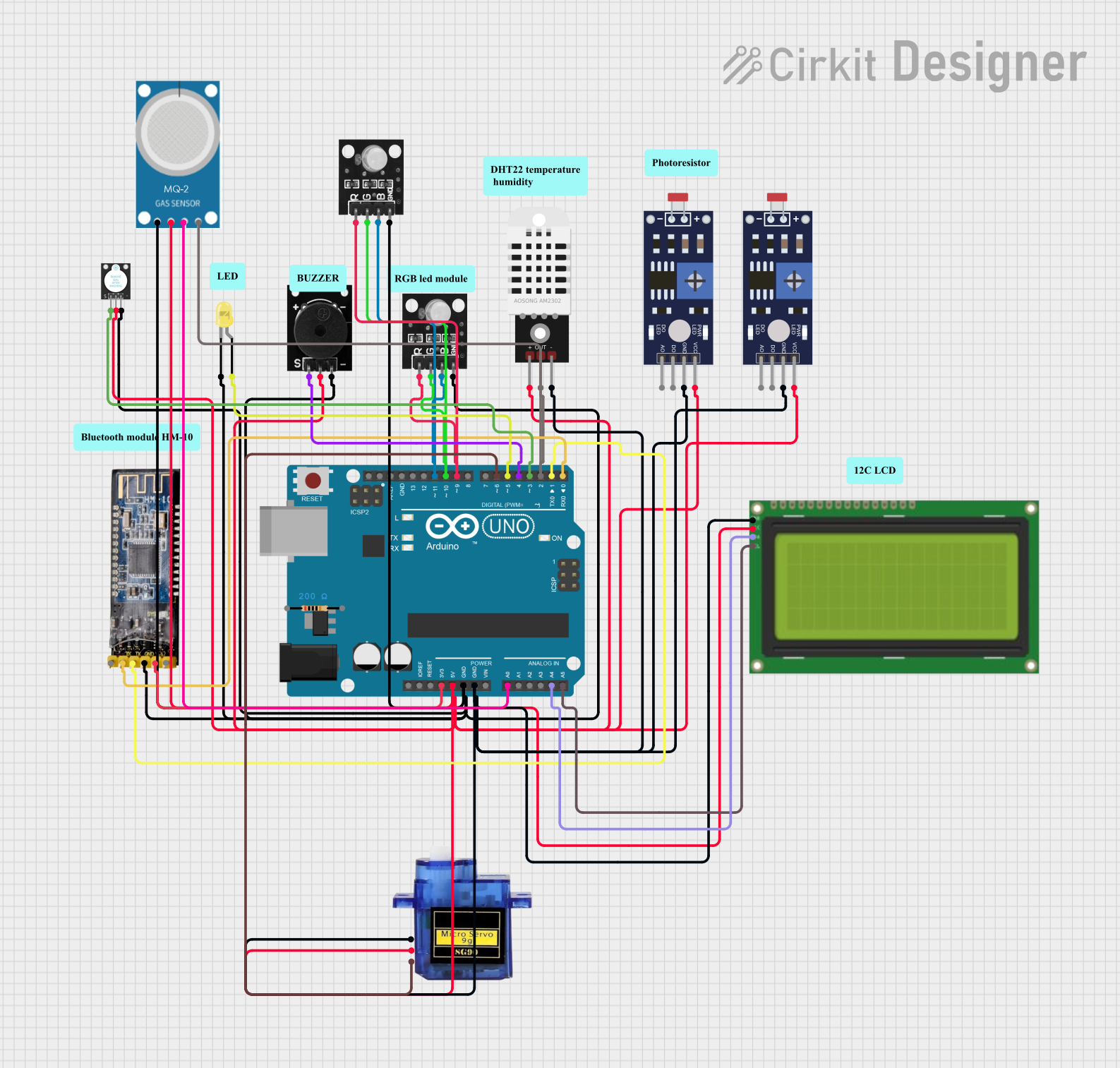 Open Project in Cirkit Designer
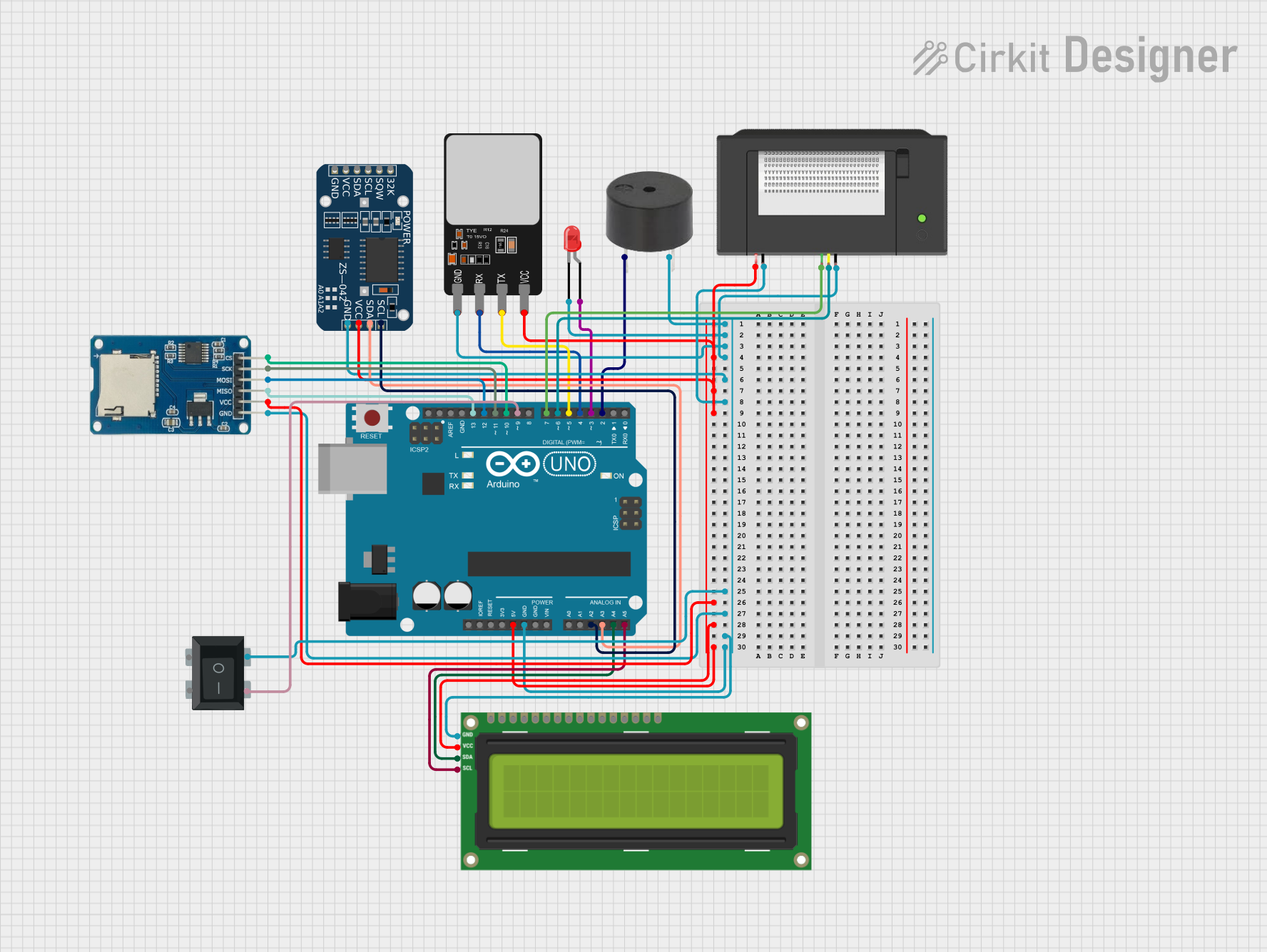 Open Project in Cirkit Designer
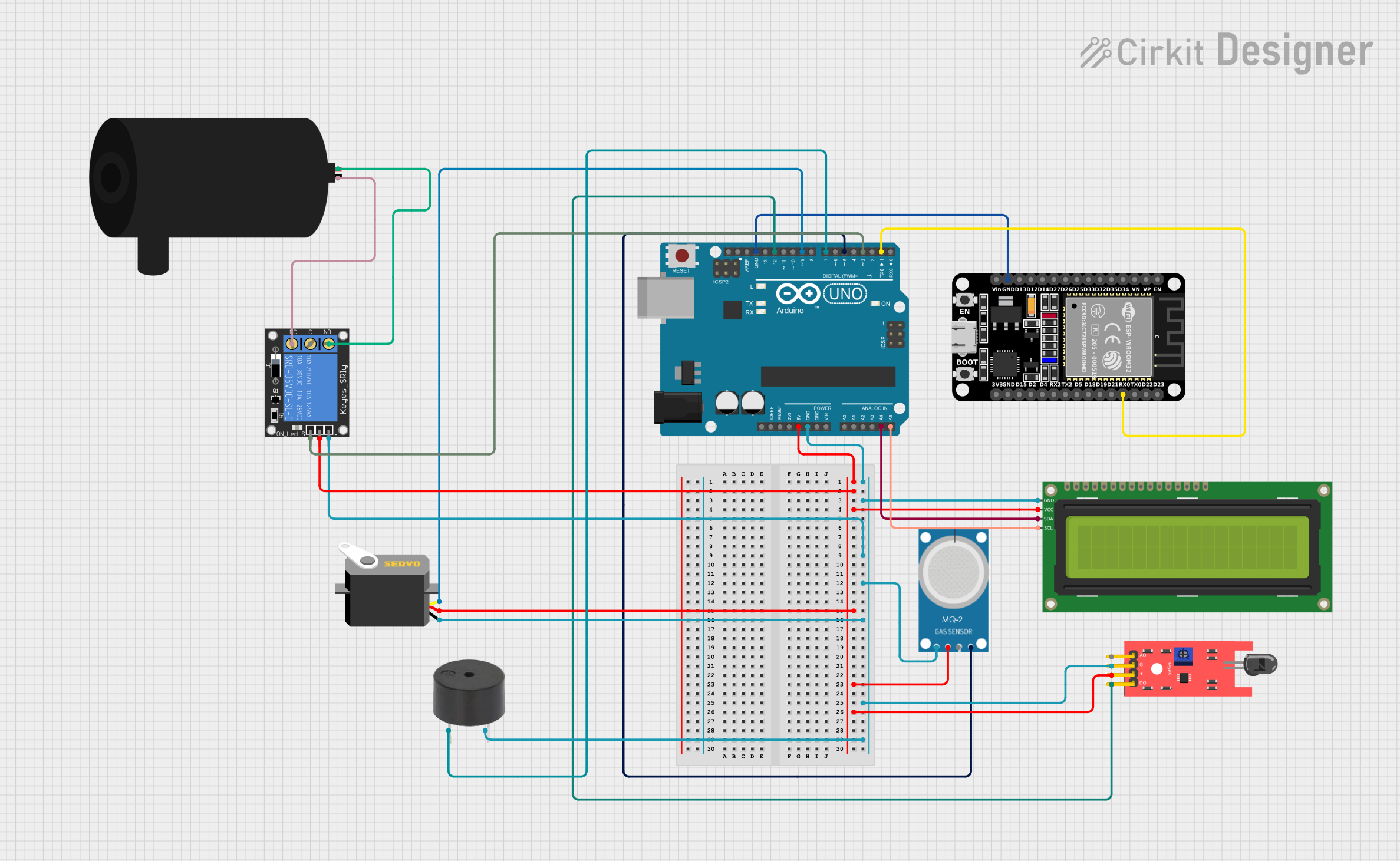 Open Project in Cirkit Designer
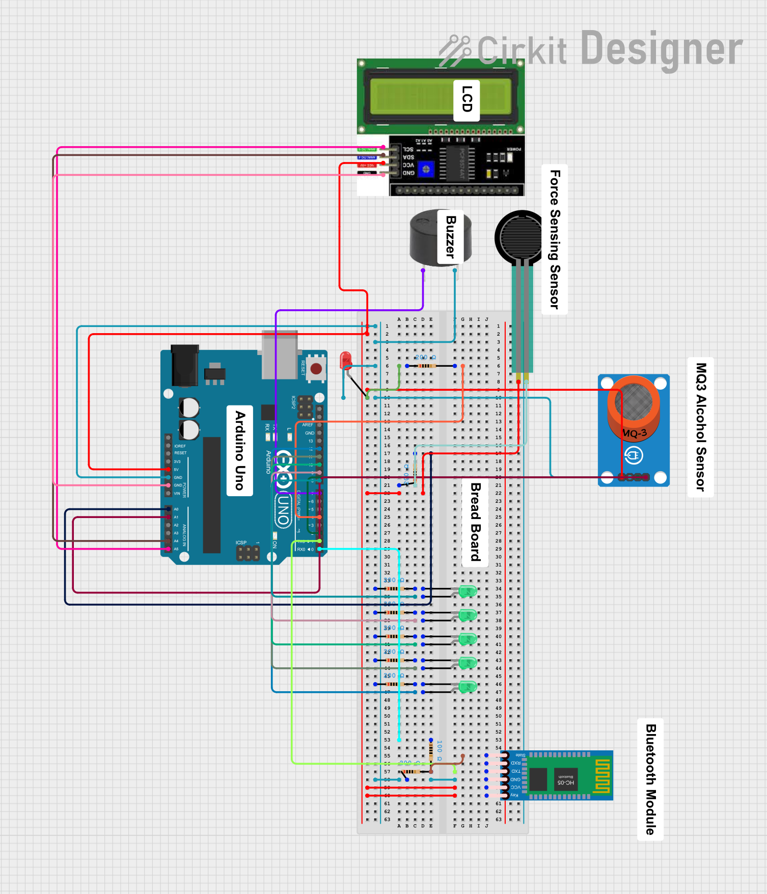 Open Project in Cirkit Designer
Explore Projects Built with Arduino UNO Q
Open Project in Cirkit DesignerOpen Project in Cirkit DesignerOpen Project in Cirkit DesignerOpen Project in Cirkit DesignerCommon Applications
- Robotics and automation
- IoT (Internet of Things) devices
- Sensor-based systems
- LED control and lighting projects
- Educational tools for learning programming and electronics
Technical Specifications
Key Technical Details
| Specification | Value |
|---|---|
| Microcontroller | ATmega328P |
| Operating Voltage | 5V |
| Input Voltage (recommended) | 7-12V |
| Input Voltage (limit) | 6-20V |
| Digital I/O Pins | 14 (6 PWM outputs) |
| Analog Input Pins | 6 |
| DC Current per I/O Pin | 20 mA |
| Flash Memory | 32 KB (0.5 KB used by bootloader) |
| SRAM | 2 KB |
| EEPROM | 1 KB |
| Clock Speed | 16 MHz |
| USB Connector | USB Type-B |
| Dimensions | 68.6 mm x 53.4 mm |
| Weight | 25 g |
Pin Configuration and Descriptions
| Pin Number | Pin Name | Description |
|---|---|---|
| 1-14 | Digital Pins | General-purpose digital I/O pins. Pins 3, 5, 6, 9, 10, and 11 support PWM. |
| A0-A5 | Analog Pins | Analog input pins for reading sensor data (10-bit resolution). |
| GND | Ground | Common ground for the circuit. |
| 5V | 5V Power | Regulated 5V output for powering external components. |
| 3.3V | 3.3V Power | Regulated 3.3V output for low-voltage components. |
| VIN | Voltage Input | Input voltage for external power supply (7-12V recommended). |
| RESET | Reset | Resets the microcontroller. |
| TX/RX | Serial Pins | TX (pin 1) and RX (pin 0) for serial communication. |
Usage Instructions
How to Use the Arduino UNO Q in a Circuit
Powering the Board:
- Connect the board to your computer using a USB Type-B cable for programming and power.
- Alternatively, use an external power supply (7-12V) via the power jack or VIN pin.
Programming the Board:
- Install the Arduino IDE from the official Arduino website.
- Connect the board to your computer and select "Arduino UNO" as the board type in the IDE.
- Write your code in the IDE and upload it to the board using the "Upload" button.
Connecting Components:
- Use the digital pins for controlling LEDs, motors, or other digital devices.
- Use the analog pins to read sensor data, such as temperature or light intensity.
- Ensure proper grounding and voltage levels to avoid damaging the board or components.
Important Considerations and Best Practices
- Avoid exceeding the maximum current rating (20 mA) for each I/O pin. Use transistors or relays for high-current loads.
- Use pull-up or pull-down resistors for stable digital input signals.
- Always double-check connections to prevent short circuits or incorrect wiring.
- Use a breadboard for prototyping to simplify connections and reduce errors.
Example Code for Arduino UNO Q
The following example demonstrates how to blink an LED connected to digital pin 13:
// This code blinks an LED connected to pin 13 on the Arduino UNO Q.
// The LED will turn on for 1 second and off for 1 second in a loop.

void setup() {
  pinMode(13, OUTPUT); // Set pin 13 as an output pin
}

void loop() {
  digitalWrite(13, HIGH); // Turn the LED on
  delay(1000);            // Wait for 1 second
  digitalWrite(13, LOW);  // Turn the LED off
  delay(1000);            // Wait for 1 second
}
Troubleshooting and FAQs
Common Issues and Solutions
The board is not detected by the computer:
- Ensure the USB cable is properly connected and functional.
- Check if the correct COM port is selected in the Arduino IDE.
- Install or update the USB drivers from the Arduino website.
Code upload fails:
- Verify that the correct board type ("Arduino UNO") is selected in the IDE.
- Press the RESET button on the board before uploading the code.
- Ensure no other program is using the same COM port.
Components not working as expected:
- Double-check the wiring and connections.
- Ensure the components are compatible with the Arduino UNO Q's voltage and current ratings.
- Test the components individually to rule out hardware issues.
FAQs
Q: Can I power the Arduino UNO Q with a battery?
A: Yes, you can use a 9V battery connected to the power jack or VIN pin. Ensure the voltage is within the recommended range (7-12V).Q: What is the difference between digital and analog pins?
A: Digital pins can only read or write HIGH (5V) or LOW (0V) signals, while analog pins can read a range of voltages (0-5V) and provide a 10-bit resolution.Q: Can I use the Arduino UNO Q for wireless communication?
A: Yes, you can connect wireless modules like Bluetooth, Wi-Fi, or RF modules to the board via the digital or serial pins.
This concludes the documentation for the Arduino UNO Q. For further assistance, refer to the official Arduino documentation.