How to Use Relay: Examples, Pinouts, and Specs
Introduction
A relay is an electrically operated switch that uses an electromagnet to mechanically operate a switching mechanism. Relays are commonly used in various applications where it is necessary to control a high-power circuit with a low-power signal. They are essential in automation, automotive, and industrial control systems.
Explore Projects Built with Relay


Explore Projects Built with Relay
Common Applications and Use Cases
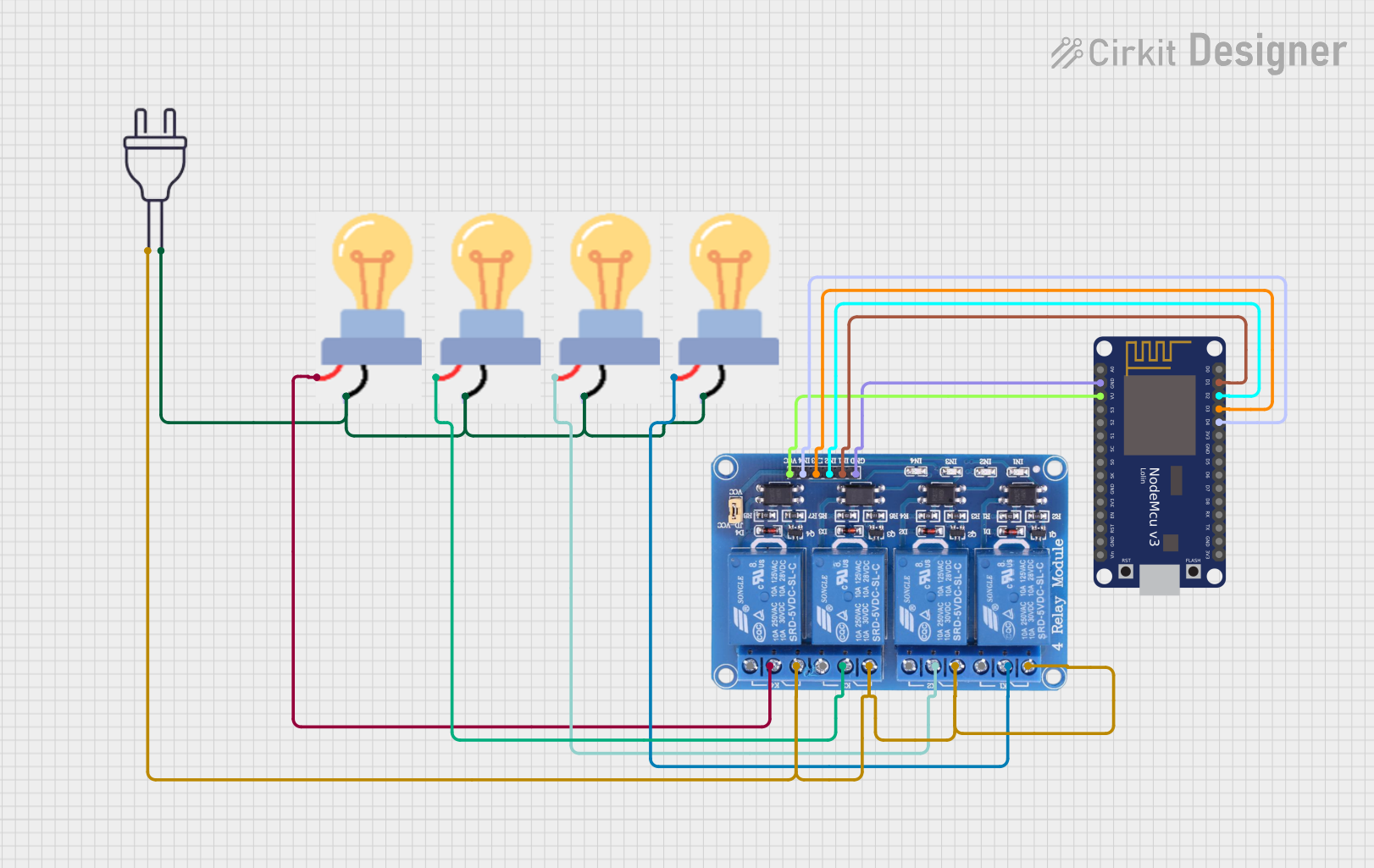
- Home Automation: Controlling lights, fans, and other household appliances.
- Automotive Systems: Switching high-current devices like headlights and horns.
- Industrial Control: Managing machinery and equipment in factories.
- Safety Systems: Isolating different parts of a circuit to prevent electrical faults.
Technical Specifications
Key Technical Details
| Parameter | Value |
|---|---|
| Coil Voltage | 5V, 12V, 24V |
| Coil Current | 70mA (5V), 30mA (12V), 15mA (24V) |
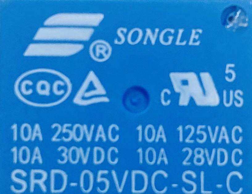
| Contact Rating | 10A @ 250VAC, 10A @ 30VDC |
| Contact Resistance | < 100mΩ |
| Operate Time | 10ms |
| Release Time | 5ms |
| Insulation Resistance | > 100MΩ @ 500VDC |
| Dielectric Strength | 500VAC between coil and contacts |
Pin Configuration and Descriptions
| Pin Number | Pin Name | Description |
|---|---|---|
| 1 | NO | Normally Open contact |
| 2 | COM | Common contact |
| 3 | NC | Normally Closed contact |
| 4 | GND | Ground |
| 5 | VCC | Voltage supply for the coil |
| 6 | IN | Control signal input |
Usage Instructions
How to Use the Component in a Circuit
Power the Relay Coil:
- Connect the VCC pin to the power supply (e.g., 5V, 12V, or 24V depending on the relay).
- Connect the GND pin to the ground of the power supply.
Control Signal:
- Connect the IN pin to the control signal source (e.g., a microcontroller like Arduino).
Switching Circuit:
- Connect the COM pin to the common point of the load.
- Connect the NO pin to the load if you want the circuit to be normally open.
- Connect the NC pin to the load if you want the circuit to be normally closed.
Important Considerations and Best Practices
- Flyback Diode: Always use a flyback diode across the relay coil to protect against voltage spikes.
- Current Rating: Ensure the relay's contact rating matches the load requirements.
- Isolation: Use optocouplers for additional isolation in sensitive applications.
- Heat Dissipation: Ensure proper ventilation to avoid overheating.
Example Circuit with Arduino UNO
/*
 * Example code to control a relay with Arduino UNO
 * The relay is connected to pin 7 of the Arduino
 */

const int relayPin = 7; // Define the relay pin

void setup() {
  pinMode(relayPin, OUTPUT); // Set the relay pin as an output
}

void loop() {
  digitalWrite(relayPin, HIGH); // Turn the relay on
  delay(1000); // Wait for 1 second
  digitalWrite(relayPin, LOW); // Turn the relay off
  delay(1000); // Wait for 1 second
}
Troubleshooting and FAQs
Common Issues Users Might Face
Relay Not Switching:
- Solution: Check the control signal voltage and ensure it matches the relay's coil voltage. Verify connections and ensure the power supply is adequate.
Chattering Relay:
- Solution: Ensure the control signal is stable and not fluctuating. Use a capacitor to filter noise if necessary.
Overheating:
- Solution: Ensure the relay is not switching a load beyond its rated capacity. Provide adequate ventilation.
Noisy Operation:
- Solution: Use a snubber circuit across the contacts to reduce arcing and noise.
FAQs
Q: Can I use a relay to switch AC and DC loads?
- A: Yes, relays can switch both AC and DC loads, but ensure the contact ratings match the load requirements.
Q: What is the purpose of the flyback diode?
- A: The flyback diode protects the circuit from voltage spikes generated when the relay coil is de-energized.
Q: How do I know if my relay is normally open or normally closed?
- A: Check the datasheet or use a multimeter to measure continuity between the COM and NO/NC pins.
This documentation provides a comprehensive guide to understanding and using relays in various applications. Whether you are a beginner or an experienced user, following these guidelines will help you effectively integrate relays into your projects.