Cirkit Designer Logo
Cirkit Designer
Your all-in-one circuit design IDE
Home / 
Component Documentation

How to Use Raspberry Pi 2A: Examples, Pinouts, and Specs

Image of Raspberry Pi 2A
Cirkit Designer LogoDesign with Raspberry Pi 2A in Cirkit Designer

Introduction

The Raspberry Pi 2A is a compact, single-board computer designed for educational purposes, hobbyists, and for use in various embedded projects. It is a cost-effective solution for those looking to learn programming, build simple embedded systems, or experiment with electronics. The Raspberry Pi 2A is known for its ease of use and versatility, making it a popular choice for a wide range of applications, from simple educational projects to more complex electronic designs.

Explore Projects Built with Raspberry Pi 2A

Use Cirkit Designer to design, explore, and prototype these projects online. Some projects support real-time simulation. Click "Open Project" to start designing instantly!
Raspberry Pi 4B with I2C Current Sensing and OLED Display
Image of iot task 2: A project utilizing Raspberry Pi 2A in a practical application
This circuit features a Raspberry Pi 4B as the central processing unit, interfaced with an Adafruit ADS1115 16-bit I2C ADC for analog-to-digital conversion and a 0.96" OLED display for visual output. The ADC is connected to a current sensor for measuring electrical current, with the sensor's output connected to the ADC's AIN0 pin and the burden resistor connected to AIN1. The Raspberry Pi communicates with both the ADC and the OLED display over the I2C bus, using GPIO2 (SDA) and GPIO3 (SCL) for data exchange.
Cirkit Designer LogoOpen Project in Cirkit Designer
Raspberry Pi 4B-Based Current Monitoring System with I2C OLED Display
Image of Virtual Energy Monitoring Circuit: A project utilizing Raspberry Pi 2A in a practical application
This circuit features a Raspberry Pi 4B as the central processing unit, interfaced with an Adafruit ADS1115 16-bit I2C ADC for analog-to-digital conversion and a 0.96" OLED display for visual output. The ADS1115 is connected to a current sensor for measuring electrical current, with the sensor's output and burden pins connected to the ADC's analog input channels. The Raspberry Pi communicates with both the ADC and the OLED display over the I2C bus, using its GPIO2 and GPIO3 pins for data (SDA) and clock (SCL) lines, respectively.
Cirkit Designer LogoOpen Project in Cirkit Designer
Raspberry Pi 4B-based Current Monitoring System with OLED Display
Image of TASK – 2: A project utilizing Raspberry Pi 2A in a practical application
This circuit features a Raspberry Pi 4B as the central processing unit, interfaced with an ADS1115 analog-to-digital converter (ADC) and a 0.96" OLED display via I2C communication (using GPIO2 and GPIO3 for SDA and SCL, respectively). The ADS1115 is connected to two current sensors: a generic current sensor and an ACS712, to measure current and report values to the Raspberry Pi, which can display the data on the OLED. Power is distributed from the Raspberry Pi's 5V pin to the other components, and all components share a common ground.
Cirkit Designer LogoOpen Project in Cirkit Designer
Raspberry Pi and ESP32 CAM-Based Weather Station with I2C Display and Sensor Integration
Image of Image restoration : A project utilizing Raspberry Pi 2A in a practical application
This circuit integrates a Raspberry Pi 2B with various sensors and an ESP32 CAM module to create a comprehensive environmental monitoring system. The Raspberry Pi collects data from a DHT11 temperature and humidity sensor, an LDR for light intensity, a rain sensor, and an ADS1115 ADC for analog inputs, while the ESP32 CAM provides camera functionality. The data is displayed on an OLED screen connected via I2C.
Cirkit Designer LogoOpen Project in Cirkit Designer

Explore Projects Built with Raspberry Pi 2A

Use Cirkit Designer to design, explore, and prototype these projects online. Some projects support real-time simulation. Click "Open Project" to start designing instantly!
Image of iot task 2: A project utilizing Raspberry Pi 2A in a practical application
Raspberry Pi 4B with I2C Current Sensing and OLED Display
This circuit features a Raspberry Pi 4B as the central processing unit, interfaced with an Adafruit ADS1115 16-bit I2C ADC for analog-to-digital conversion and a 0.96" OLED display for visual output. The ADC is connected to a current sensor for measuring electrical current, with the sensor's output connected to the ADC's AIN0 pin and the burden resistor connected to AIN1. The Raspberry Pi communicates with both the ADC and the OLED display over the I2C bus, using GPIO2 (SDA) and GPIO3 (SCL) for data exchange.
Cirkit Designer LogoOpen Project in Cirkit Designer
Image of Virtual Energy Monitoring Circuit: A project utilizing Raspberry Pi 2A in a practical application
Raspberry Pi 4B-Based Current Monitoring System with I2C OLED Display
This circuit features a Raspberry Pi 4B as the central processing unit, interfaced with an Adafruit ADS1115 16-bit I2C ADC for analog-to-digital conversion and a 0.96" OLED display for visual output. The ADS1115 is connected to a current sensor for measuring electrical current, with the sensor's output and burden pins connected to the ADC's analog input channels. The Raspberry Pi communicates with both the ADC and the OLED display over the I2C bus, using its GPIO2 and GPIO3 pins for data (SDA) and clock (SCL) lines, respectively.
Cirkit Designer LogoOpen Project in Cirkit Designer
Image of TASK – 2: A project utilizing Raspberry Pi 2A in a practical application
Raspberry Pi 4B-based Current Monitoring System with OLED Display
This circuit features a Raspberry Pi 4B as the central processing unit, interfaced with an ADS1115 analog-to-digital converter (ADC) and a 0.96" OLED display via I2C communication (using GPIO2 and GPIO3 for SDA and SCL, respectively). The ADS1115 is connected to two current sensors: a generic current sensor and an ACS712, to measure current and report values to the Raspberry Pi, which can display the data on the OLED. Power is distributed from the Raspberry Pi's 5V pin to the other components, and all components share a common ground.
Cirkit Designer LogoOpen Project in Cirkit Designer
Image of Image restoration : A project utilizing Raspberry Pi 2A in a practical application
Raspberry Pi and ESP32 CAM-Based Weather Station with I2C Display and Sensor Integration
This circuit integrates a Raspberry Pi 2B with various sensors and an ESP32 CAM module to create a comprehensive environmental monitoring system. The Raspberry Pi collects data from a DHT11 temperature and humidity sensor, an LDR for light intensity, a rain sensor, and an ADS1115 ADC for analog inputs, while the ESP32 CAM provides camera functionality. The data is displayed on an OLED screen connected via I2C.
Cirkit Designer LogoOpen Project in Cirkit Designer

Common Applications and Use Cases

  • Learning to program in languages such as Python, Scratch, and others
  • DIY projects like home automation, weather stations, and media centers
  • Prototyping for embedded systems
  • Basic web servers or network-attached storage (NAS) devices
  • Educational tools for schools and workshops

Technical Specifications

Key Technical Details

  • Processor: Single-core ARM1176JZF-S
  • RAM: 512MB
  • Networking: 10/100 Ethernet Port
  • USB: 2 USB 2.0 ports
  • GPIO: 40-pin header, fully backward-compatible with previous boards
  • Storage: MicroSD slot for loading the operating system and data storage
  • Video Output: HDMI and Composite RCA
  • Audio Output: 3.5mm jack and HDMI
  • Power Input: Micro USB socket 5V, 2A

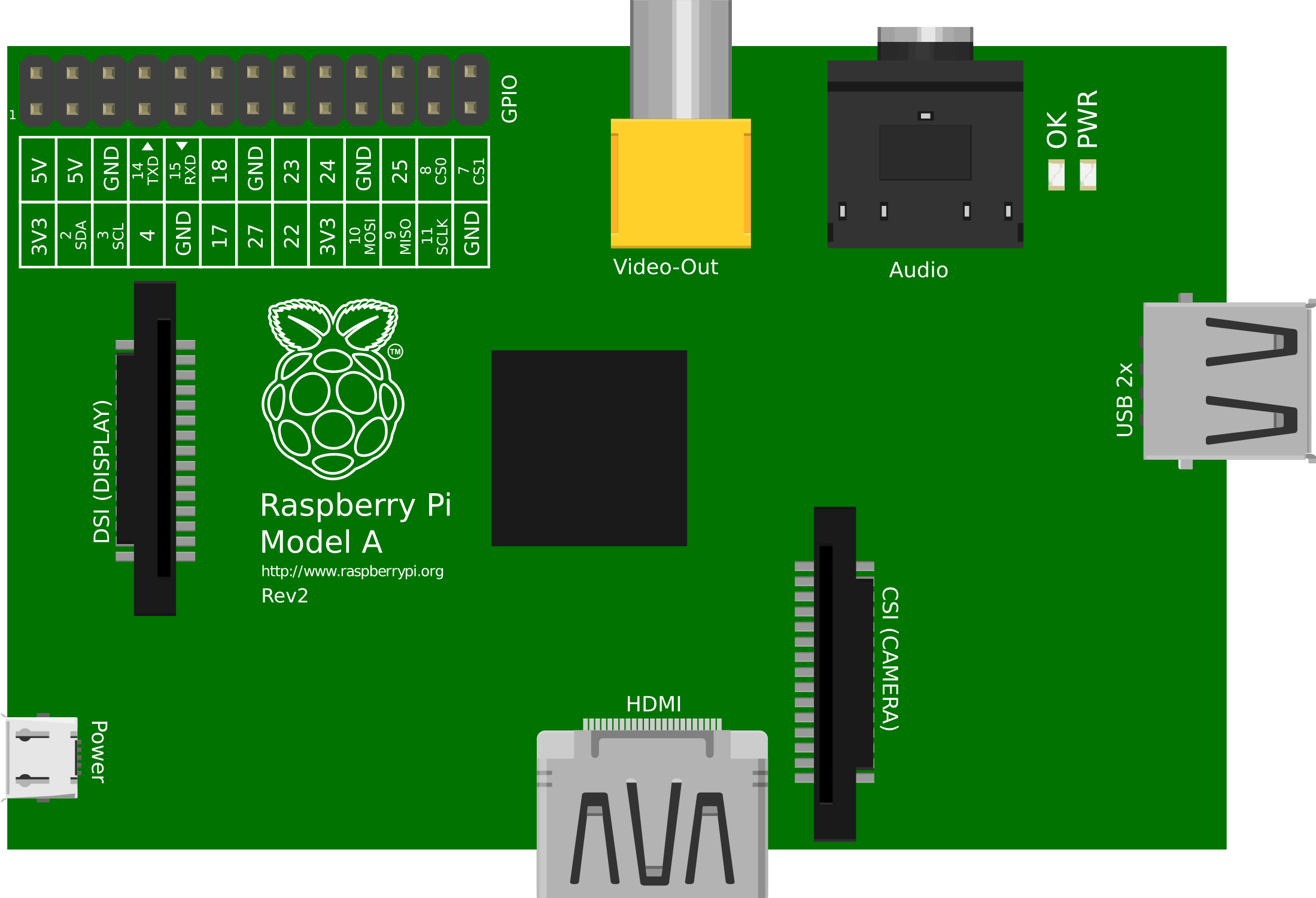
Pin Configuration and Descriptions

Pin Number Description Pin Number Description
1 3.3V Power 2 5V Power
3 GPIO 2 (SDA1, I2C) 4 5V Power
5 GPIO 3 (SCL1, I2C) 6 Ground
... ... ... ...
39 Ground 40 GPIO 21 (SPI0_MISO)

Note: This table is not exhaustive. Refer to the Raspberry Pi GPIO documentation for the complete pinout.

Usage Instructions

How to Use the Raspberry Pi 2A in a Circuit

  1. Power Supply: Connect a 5V, 2A micro USB power supply to the Raspberry Pi 2A to power it up.
  2. MicroSD Card: Insert a preloaded microSD card with the desired operating system into the microSD slot.
  3. Peripherals: Connect peripherals such as a keyboard, mouse, and monitor to the USB ports and HDMI port, respectively.
  4. Networking: Use the Ethernet port for network connectivity or connect a USB Wi-Fi adapter.
  5. GPIO Pins: Interface with electronic components using the GPIO pins, ensuring that the voltage levels are compatible.

Important Considerations and Best Practices

  • Always power down the Raspberry Pi before connecting or disconnecting components to avoid damage.
  • Use a reliable power supply to prevent unexpected shutdowns and data corruption.
  • Regularly update the operating system and software to ensure security and stability.
  • Employ proper static electricity precautions when handling the Raspberry Pi and electronic components.
  • Utilize heat sinks or cooling solutions if the Raspberry Pi is operating under heavy load or in high-temperature environments.

Troubleshooting and FAQs

Common Issues Users Might Face

  • Raspberry Pi not booting: Ensure the microSD card is properly inserted and contains a bootable operating system. Check the power supply and cables.
  • No video output: Verify that the HDMI cable is securely connected and that the monitor is functioning. Try a different screen or cable if necessary.
  • Overheating: Make sure the Raspberry Pi is in a well-ventilated area. Consider using heat sinks or a fan.

Solutions and Tips for Troubleshooting

  • LED Indicators: The Raspberry Pi has several onboard LEDs that can help diagnose issues. A steady red light typically indicates proper power, while a flashing green light indicates SD card activity.
  • Reflashing the SD Card: If the Raspberry Pi fails to boot, try reflashing the microSD card with the operating system.
  • Network Connectivity: If you're having trouble with the Ethernet connection, check the cable and router settings. For Wi-Fi issues, ensure that the USB Wi-Fi adapter is compatible and properly configured.

Code Example for Raspberry Pi 2A

Here is a simple Python script to blink an LED connected to the GPIO pin 21 on the Raspberry Pi 2A. This assumes you have the RPi.GPIO library installed.

import RPi.GPIO as GPIO
import time

Set up the GPIO channel

GPIO.setmode(GPIO.BCM) # Use Broadcom pin numbering GPIO.setup(21, GPIO.OUT) # Set GPIO pin 21 to output mode

try: while True: GPIO.output(21, GPIO.HIGH) # Turn on the LED time.sleep(1) # Wait for one second GPIO.output(21, GPIO.LOW) # Turn off the LED time.sleep(1) # Wait for one second except KeyboardInterrupt: GPIO.cleanup() # Clean up GPIO on CTRL+C exit

GPIO.cleanup() # Clean up GPIO on normal exit


*Note: This code is for demonstration purposes and assumes that the user has basic knowledge of setting up the Raspberry Pi and running Python scripts.*

Remember to always check the Raspberry Pi's GPIO pinout and ensure you're connecting the LED to the correct pin with a suitable resistor to limit the current.